Chapter 4 Addendum Operating Instructions
S3000 in a narrow aisle
12 © SICK AG • Industrial Safety Systems • Germany • All rights reserved 8012793/TL59/2010-01-29
Subject to change without notice
Installation and commissioning
Required protective field length L
P
F
:
– Left half of the protective field:
L
P
F
=
L
S
top
× 1.1 + L
F
ork
+ S
P
F, 100 cm
= 350 × 1.1 + 120 + 70 = 575 cm
– Right half of the protective field:
L
PF
= L
Stop
× 1.1 + L
Fork
+ S
PF, 150 cm
= 350 × 1.1 + 120 + 90 = 595 cm
The larger value is to be used for the right half of the protective field L
P
F
= 595 cm. The
permissible protective field length for the right half of the protective field is L
max
= 623
cm, see Tab. 1.
During the configuration of the S3000 using the user software S3000 (see section 4.3
“Operating mode of the S3000” on page 8), the application variant “mobile” is to be
set.
If it is not possible to program a permissible corner point because the permissible
protective field length L
max
or the maximum measuring radius of 700 cm is exceeded,
then with a constant X value, reduce the Y position until a permissible value L
max
is
achieved. The programmed protective field length and width must always be larger or
equal to that required. The protective field width on the right or left can, if necessary, be
changed by slightly moving the S3000 transverse to the direction of travel of the
industrial truck and as a result the necessary protective field length then programmed.
For the left half of the protective field the following is found:
– On the entry of set values X
PF
= –90.5 and Y
PF
= 0, the value is rounded up to the
next largest safety-related value X
P
F
= –91 cm.
– On the entry of the set values X
PF
= –91.5 and Y
PF
= 598, the values X = –92.0 and
Y = 598 are found.
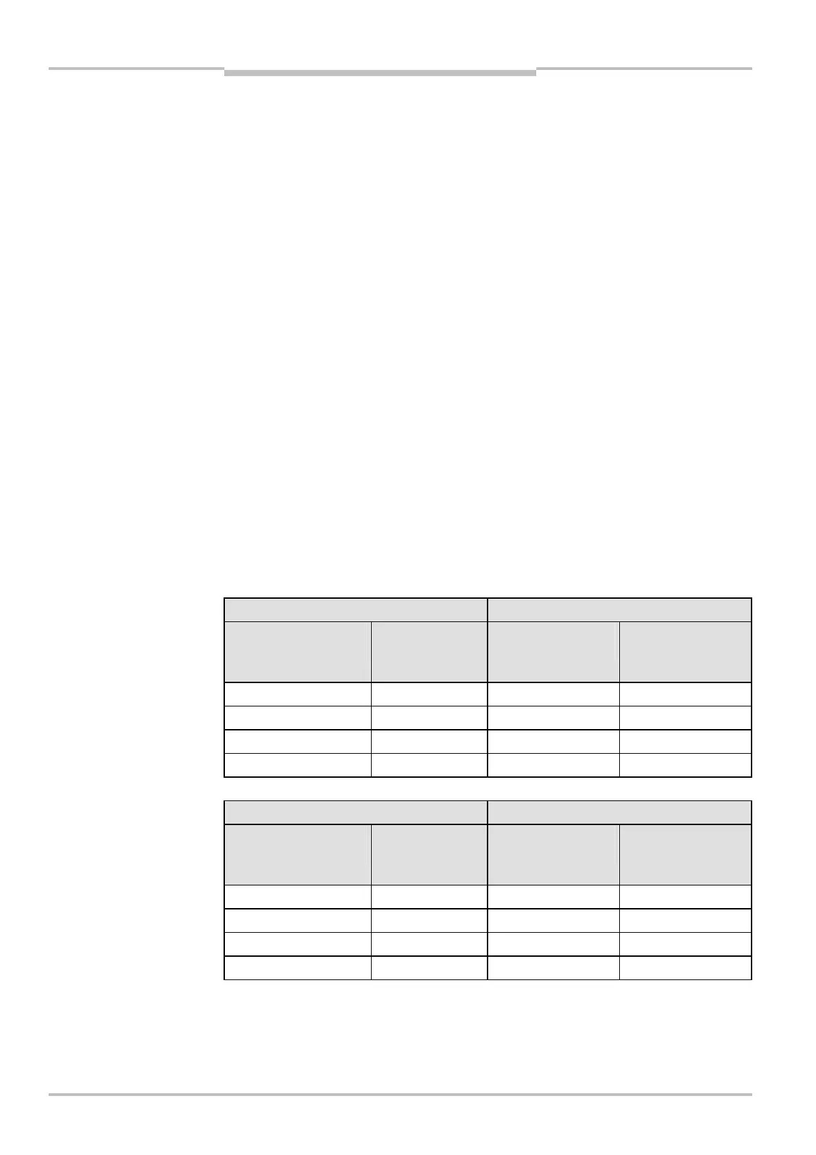
The permissible and programmable co-ordinates for the protective field corner points
are summarised in Tab. 2 and Tab. 3.
Entries in CDS Values realised by CDS
D
S3000–Shelf
– D
PF–Shelf
[cm]
Protective field
length
[cm]
Position X
[cm]
Position Y
[cm]
–100 + 9.5 = –90.5 0 –91 0
–100 + 9.5 = –90.5 100 –90.3 100.3
–100 + 8.5 = –91.5 200 –91.2 200.2
–100 + 8.5 = –91.5 598 –92.0 598.0
Entries in CDS Values realised by CDS
D
S3000–Shelf
– D
PF–Shelf
[cm]
Protective field
length
[cm]
Position X
[cm]
Position Y
[cm]
120 – 9.5 = 110.5 0 111 0
120 – 9.5 = 110.5 100 110.6 101.3
120 – 9 = 111 200 111 200.3
120 – 9 = 111 598 111 598.8
the left half of the protective
field
the right half of the protective
field

 Loading...


