b
S
elect the mounting location so that the sensor and actuator are accessible for
maintenance work and are protected against damage.
b
Mount the sensor and actuator on a non-ferrous surface and at a distance from
metal parts if possible in order to avoid influencing the sensing range. If this is not
possible, the influence on the assured switch-on distance S
ao
and the assured
switch-off distance S
ar
must be checked.
b
When the guard is closed, the sensor and actuator must be located opposite each
other in the assured switch-on distance 0.8 × S
ao
or closer. A minimum distance
must be observed if the approach direction is from the side (see "Technical data",
page 36).
NOTE
In t
he case of flush installation, the sensing range changes based on the installa‐
tion depth and the material of the guard.
b
The switching operation must be triggered only by the actuator specifically
intended for this.
b
Make sure that all dangerous states are excluded when the guard is opened, even
if the actuator has not yet reached the assured switch-off distance S
ar
.
NOTE
A
t the assured switch-off distance S
ar
, the safety outputs (relay outputs) are reli‐
ably switched off even in the event of an internal component failure.
b
T
he sensor and actuator must not be used as a mechanical stop. If necessary, fit
an additional stop for the movable physical guard.
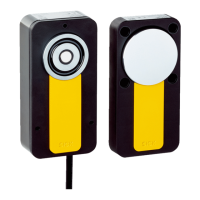
Mounting the sensor
b
Mount t
he sensor on the fixed part of the guard, e.g. using the supplied safety
screws.
b
Tightening torque: 1 Nm
Mounting the actuator
b
Align the actuator to the sensor.
b
Actuators must be positively connected to the guard, e.g. using the supplied safety
screws.
b
It must not be possible to remove or manipulate actuators by simple means.
b
Tightening torque: 1 Nm
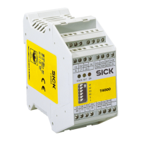
Mounting the evaluation unit
b
The evaluation unit must be installed in a control cabinet with an enclosure rating
of at least IP54.
b
A latching element on the rear of the device is used for mounting on a mounting
rail.
b
If several evaluation units are mounted next to each other in a control cabinet
without air circulation (e.g. ventilator) between the evaluation units, observe a dis‐
tance of 10 mm for heat dissipation.
MOUNTING 5
8022726/2019-05-07 | SICK O P E R A T I N G I N S T R U C T I O N S | T4000 Multi
21
Subject to change without notice