6.3 Sensor connection
1. The connecting cable of the sensor must not be extended.
2.
The shield of the sensor cable (strip max. 3 cm) must be connected with connec‐
tion SH1 … 4 of the evaluation unit.
3. The screws of the terminals must be tightened with a tightening torque of 0.6–
0.8 Nm.
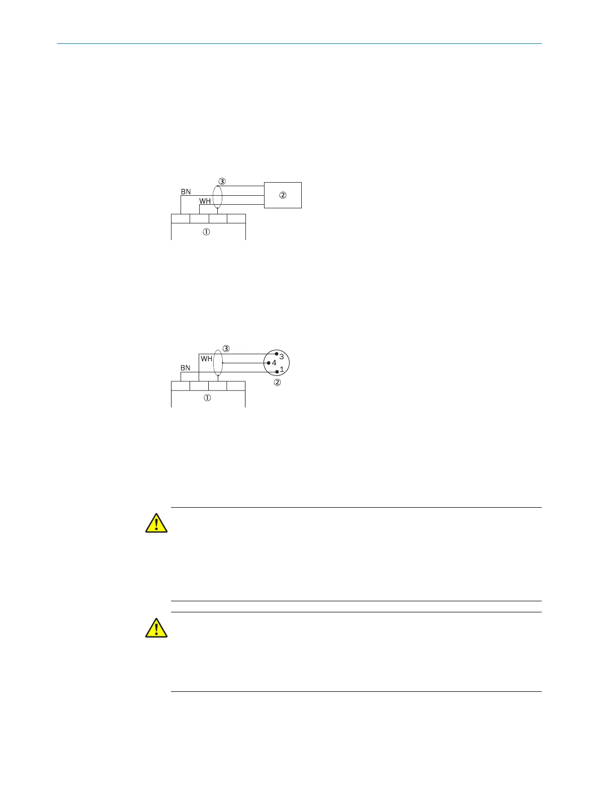
Sensor T4000-DNA..P (with permanently connected cable)
Figure 6: Pin assignment T4000-DNA..P
1
Evaluation unit
2
Plug connector M8 of the sensor
3
Shield
Sensor T4000-DNAC with plug connector M8, 3-pin (with latching and screw connec‐
t
ion)
Figure 7: Pin assignment T4000-DNAC
1
Evaluation unit
2
Sensor
3
Shield
6.4 Evaluation unit connection
DANGER
Im
proper use of the safety switch
Risk of ineffectiveness of the protective device
The dangerous state may not be stopped in the event of non-compliance.
b
Both safety outputs (relay outputs) 13/14 and 23/24 must always be evaluated in
order to guarantee safety.
DANGER
Im
proper use of the safety switch
Risk of ineffectiveness of the protective device
b
The application diagnostic outputs 01 … 02 or 01 … 04 must not be used as
safety outputs.
b
T
ighten the screws of the terminals with a tightening torque of 0.6–0.8 Nm.
b
Protect the voltage supply before terminal UB with a fuse that has a maximum rat‐
ing of 8 A.
6 ELE
CTRICAL INSTALLATION
24
O P E R A T I N G I N S T R U C T I O N S | T4000 Multi 8022726/2019-05-07 | SICK
Subject to change without notice