b
Pr
ovide a sufficient suppressor circuit for all output contacts for capacitive and
inductive loads.
b
If the device does not respond when the supply voltage is connected (e.g. green
LED STATE does not light up), return the device to the manufacturer unopened.
NOTE
•
T
he supply voltage UB is reverse polarity protected.
•
A cross-circuit between 13/14 and 23/24 can be detected only by external clock‐
ing.
•
The application diagnostic output DIA and the sensor connections (H1a/H1b,
H2a/H2b, H3a/H3b and H4a/H4b) are not short-circuit protected.
•
The application diagnostic outputs 01 … 02 or 01 … 04 are short-circuit protected,
but are not overload-proof.
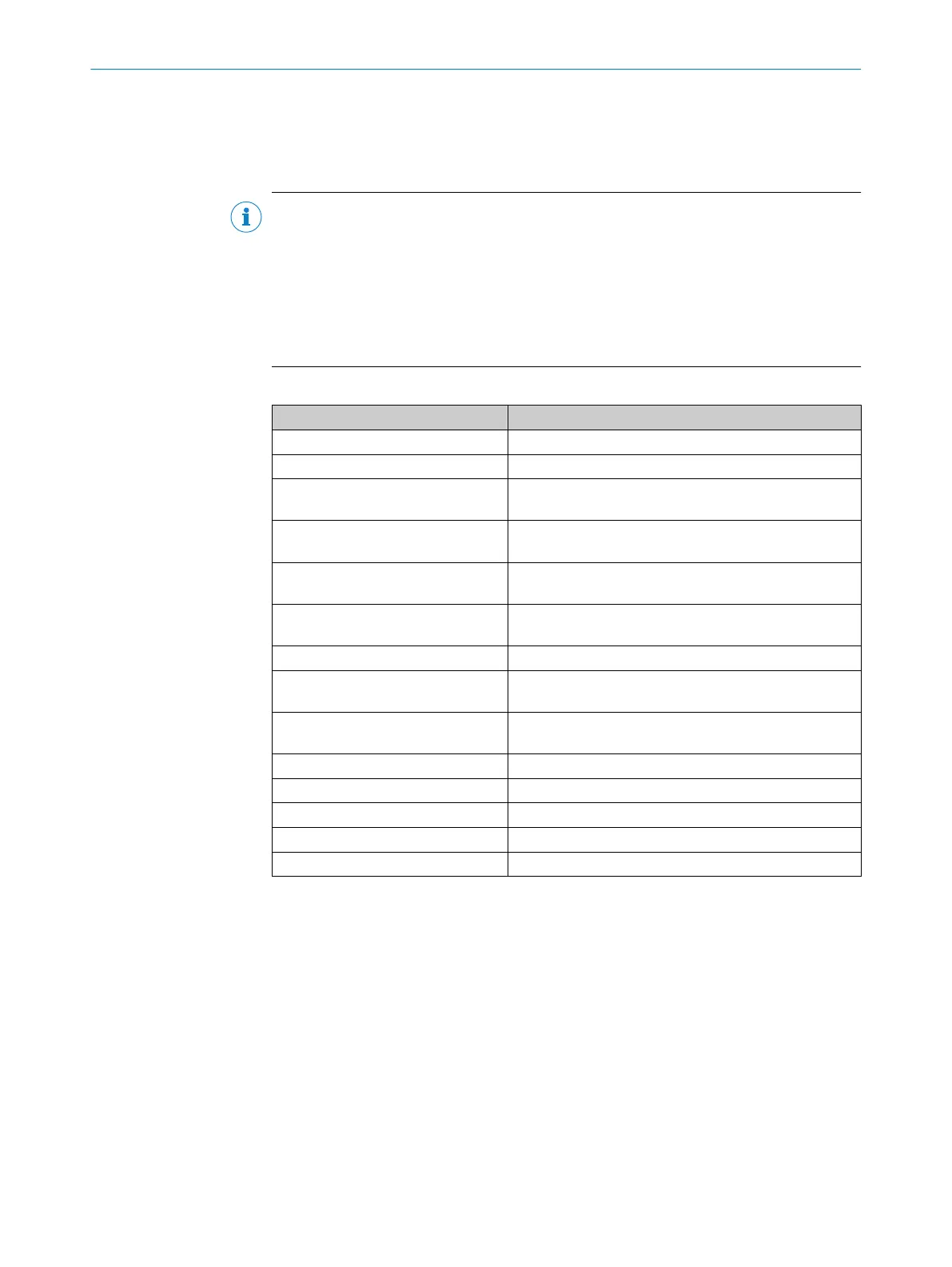
Table 2: Terminal assignment of the evaluation unit
Terminal Assignment
+UB, 0 V Supply voltage
J1, J2 Shorting jumper for teach-in process
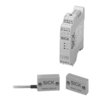
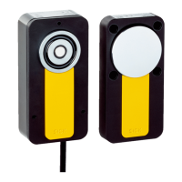
H1a/H1b … H2a/H2b Connection of sensors 1 … 2 for evaluation unit
T4000-1R
CA02
H1a/H1b … H4a/H4b Connection of sensors 1 … 4 for evaluation unit
T4000-1R
CA04
SH1 … SH2 Shield connection of sensors 1 … 2 for evaluation unit
T4000-1R
CA02
SH1 … SH4 Shield connection of sensors 1 … 4 for evaluation unit
T4000-1RCA04
TST Test input
01 … 02 Application diagnostic outputs of sensors 1 … 2 for eval‐
ua
tion unit T4000-1RCA02
01 … 04 Application diagnostic outputs of sensors 1 … 4 for eval‐
uation unit T4000-1RCA04
DIA Diagnostic output
13/14 Relay contact A connection, safety relay enable
23/24 Relay contact B connection, safety relay enable
Y1, Y2 External device monitoring (EDM) connection
S Reset pushbutton connection
ELECTRICAL INSTALLATION 6
8022726/2019-05-07 | SICK O P E R A T I N G I N S T R U C T I O N S | T4000 Multi
25
Subject to change without notice