14 List of figures
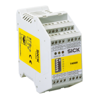
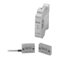
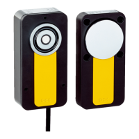
1. Components of the T4000 Multi transponder safety switch................................... 10
2. Electrical diagram of external device monitoring (EDM)..........................................16
3. Connection example T4000-1RCA02........................................................................17
4. Connection example T4000-1RCA04........................................................................18
5. Minimum distance when several safety switches are mounted..............................22
6. Pin assignment T4000-DNA..P.................................................................................. 24
7. Pin assignment T4000-DNAC.................................................................................... 24
8. Block diagram with two sensors................................................................................26
9. Block diagram with four sensors............................................................................... 27
10. Typical response range for cable length l = 0 to 25 m ...........................................38
11. Dimensional drawing for evaluation units T4000-1RCA02 and
T4000-1R
CA04 (mm)................................................................................................. 40
12. Dimensional drawing of sensor T4000-DNA..P (mm).............................................. 40
13. Dimensional drawing of sensor T4000-DNAC (mm)................................................ 41
14. Dimensional drawing of actuator T4000-1KBA (mm).............................................. 41
14 LIS
T OF FIGURES
44
O P E R A T I N G I N S T R U C T I O N S | T4000 Multi 8022726/2019-05-07 | SICK
Subject to change without notice