•
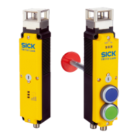
The pushbuttons contain single-channel normally open contacts which can be
used to trigger control signals.
•
LEDs are located in the pushbuttons which can be controlled, e.g. to signal opera‐
tional statuses.
•
The pushbuttons can be assigned colors using cover caps.
The TR110 Lock safety locking device with pushbuttons differs between the following
variants:
•
Power to lock principle
•
Power to release principle
•
Power to release principle with escape release
Further topics
•
"Ordering information", page 62
3.2.2 OSSD
Output signal switching device: signal output for the protective device, which is used for
stopping the dangerous movement.
An OSSD is a safety switching output. The functionality of each OSSD is tested periodi‐
cally. OSSDs are always connected in pairs and must undergo dual-channel analysis for
safety reasons. An OSSD pair is formed from 2 OSSDs that are connected and analyzed
together.
3.2.3 Application diagnostic outputs
Important information
NOTE
In the case of safety locking devices cascaded with T-connectors, the locking function
application diagnostic output (Out AUX LOCK) cannot be evaluated.
Different application diagnostic outputs
Depending on the device connection, the variants feature various application diagnostic
outputs.
•
Door application diagnostic output (Out AUX DOOR)
•
Locking device application diagnostic output (Out AUX LOCK)
•
Diagnostic application diagnostic output (Out AUX DIA)
3.2.4 Status indicators
The safety locking device indicates status information using multiple LEDs.
3 PRODUCT DESCRIPTION
10
O P E R A T I N G I N S T R U C T I O N S | TR110 Lock 8023119/15LY/2019-10-28 | SICK
Subject to change without notice