Wiring the CAN interface of the device via a connection module:
Connection modules Interface Reference
CDB650-204 CAN see "Wiring the CAN interface in the
CDB650-204", page 59
CDM420-0006 CAN see "Wiring the CAN interface in the
CDM420-0006", page 67
6.5.5 Wiring the digital inputs
Physical digital inputs on the device
The full complement of digital inputs is available at each of the following locations:
•
Male connector of the device (M12, 17-pin, A-coded)
•
Adapter cable (female connector, M12, 17-pin, A-coded/male connector, D-Sub-
HD, 15-pin)
•
Open end of the adapter cable (female connector, M12, 17-pin, A-coded/open
end)
Function assignment
NOTE
Control the digital inputs in the device with the API functions. In order to assign the digi‐
tal inputs functions, use an installed SensorApp which contains this function.
6.5.6 Wiring the digital outputs
Physical digital outputs on the device
The full complement of digital outputs is available at each of the following locations:
•
Male connector of the device (M12, 17-pin, A-coded)
•
Open end of the adapter cable (female connector, M12, 17-pin, A-coded/open
end)
•
CDB650-204 connection module
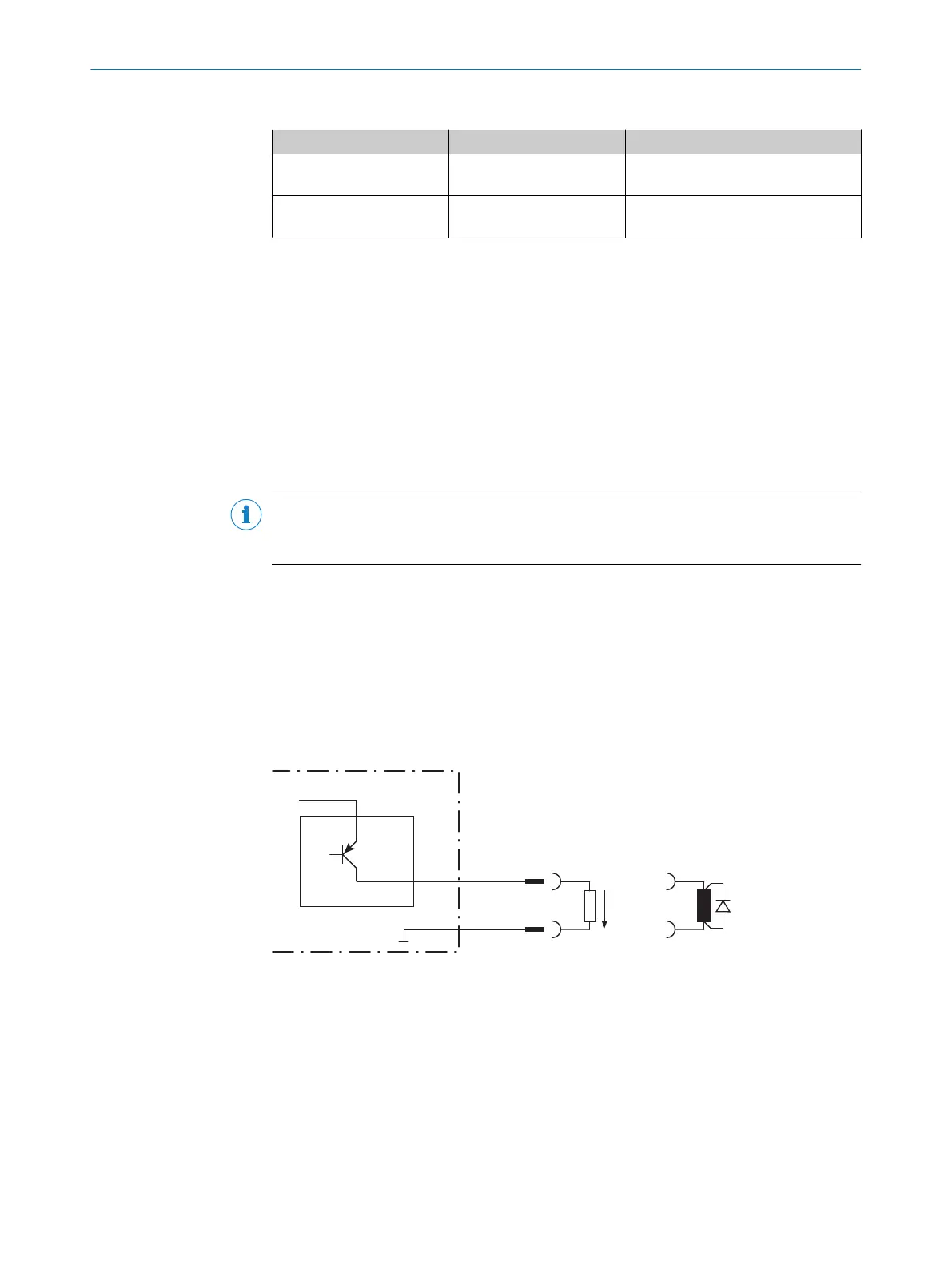
V
out
3
4
Switching output of device 1
!
"
Signal 2
GND
Figure 21: Wiring a digital output
1
2
Output signal
3
Output voltage V
out
4
With inductive load: see note
!... "
For pin assignment, see respective device
6 ELECTRICAL INSTALLATION
38
O P E R A T I N G I N S T R U C T I O N S | InspectorP621 8024439//2019-06 | SICK
Subject to change without notice
 Loading...

