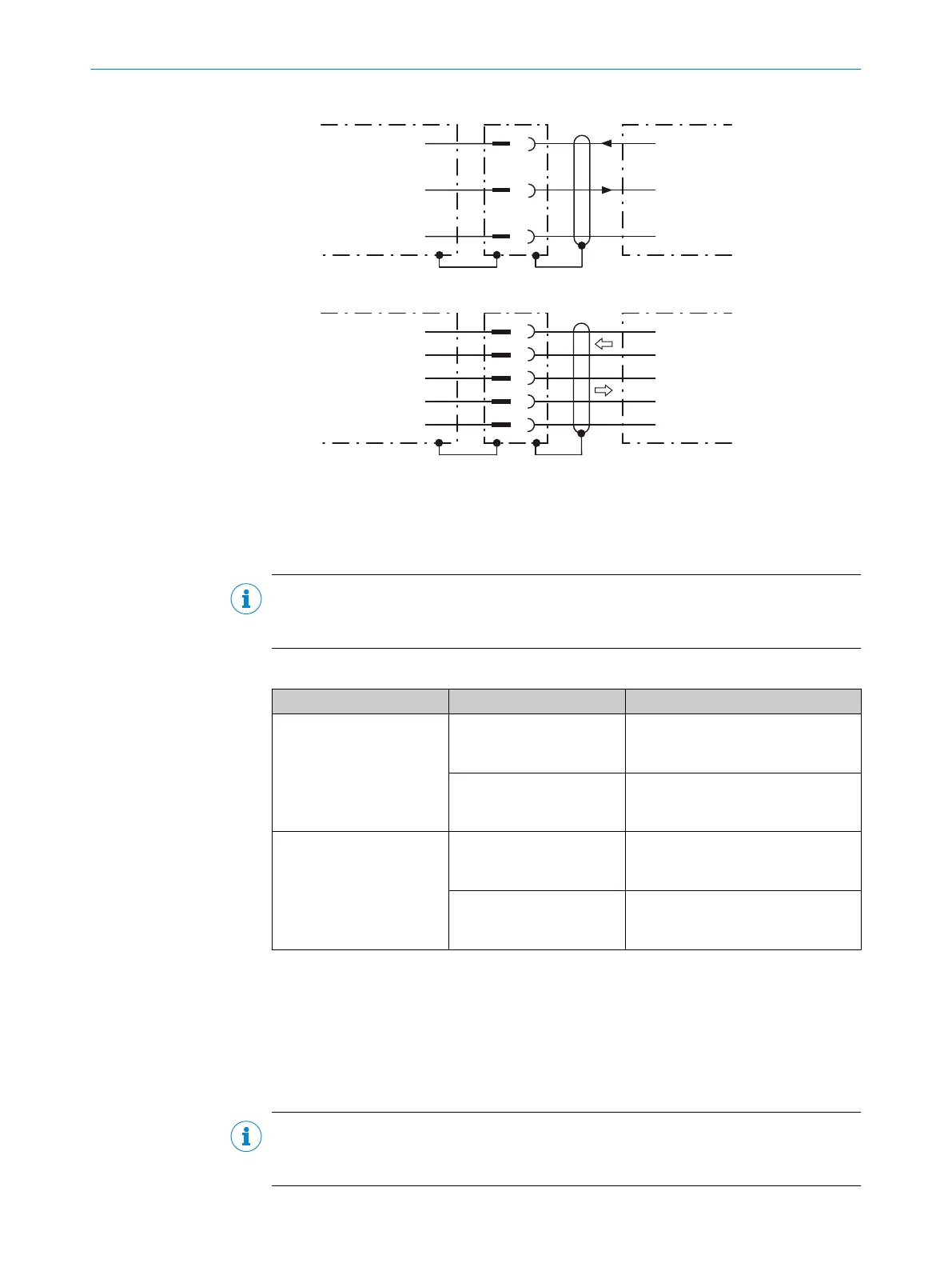
RS-232
!
"
§
Device 1 Host
TxD
RxD
GND
RxD
TxD
GND
RS-422
$
%
&
/
(
Device 1 Host
RD+
TD+
RD‒
TD‒
GND
TD+
RD+
TD‒
RD‒
GND
Figure 20: Wiring of the serial data interfaces RS-232 and RS-422
1
Device
!...§
Pin assignment: see RS-232 pin assignment for the respective device
$...(
Pin assignment: see RS-422 pin assignment for the respective device
NOTE
Control the serial data interface in the device with the API functions. In order to activate
the serial data interface, use an installed SensorApp which contains this function.
Wiring the data interfaces of the device via a connection module:
Connection module Data interface Reference
CDB650-204 RS-232 see "Wiring serial host interface
RS-232 of the device in
CDB650-204", page 57
RS-422 see "Wiring serial host interface
RS-422 of the device in
CDB650-204", page 58
CDM420-0006 RS-232 see "Connecting serial host interface
RS-232 of the device in
CDM420-0006", page 66
RS-422 see "Connecting serial host interface
RS-422 of the device in
CDM420-0006", page 66
Termination of the RS-422/485 data interface
Termination can be implemented in the connection module via switches.
Additional information on this can be found in the operating instructions for the relevant
connection module.
6.5.4 Wiring the CAN interface
NOTE
Control the CAN interface in the device with the API functions. In order to activate the
CAN interface, use an installed SensorApp which contains this function.
ELECTRICAL INSTALLATION 6
8024439//2019-06 | SICK O P E R A T I N G I N S T R U C T I O N S | InspectorP621
37
Subject to change without notice
 Loading...

