3
CMC600 parameter cloning module (not supported)
4
Auxiliary interface “Aux”
5
Male connector, D-Sub, 9-pin
6
Name of the digital output
7
e.g. PLC (programmable logic controller)
8
SCANNER = Device
9
Female connector, D-Sub-HD, 15-pin
ß
Device to be connected
à
External digital inputs and outputs of the device (not supported).
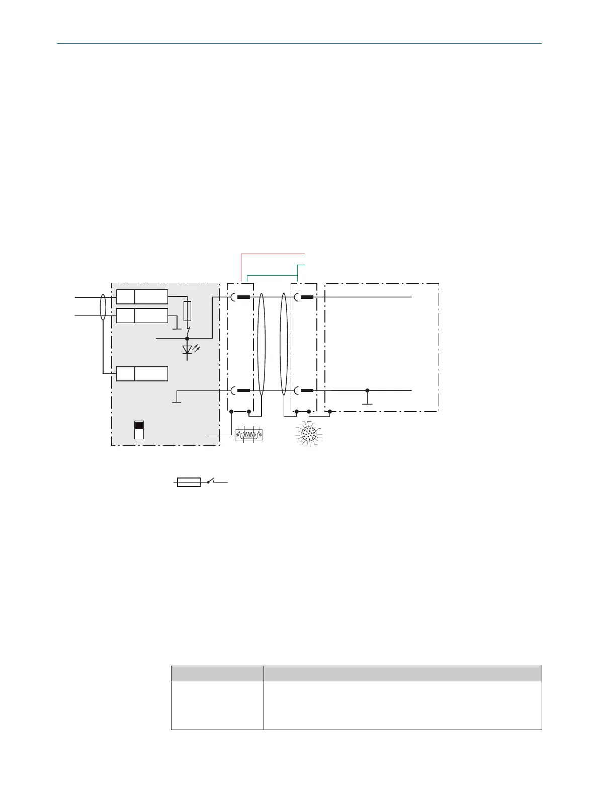
13.4.3 Connecting supply voltage for the device in CDM420-0006
Device
4CDM420-0006
V
S
2
1
1
5
5
Shield
1 +24 V
2 GND
+24 V*
GND
S1
F
Shield
GND
.
.
.
.
.
.
.
.
.
ON
OFF
S1 : POWER
+24 V*
POWER
V
S
GND
3
1
7
2
6
5
4
8
13
14
17
15
9
10
12
16
11
V
S
- +24 V -
F
S 1
- +24 V*
6 5
V
s
1
110
15
6
11
5
Cable 2
Cable 3
Figure 35: Connecting supply voltage for the device in CDM420-0006 connection module
1
Supply voltage V
S
2
Adapter cable (male connector, D-Sub-HD, 15-pin / female connector, M12, 17-pin, A-coded)
3
Adapter cable (male connector, D-Sub-HD, 15-pin / female connector, M12, 17-pin, A-coded)
4
Device
5
Male connector, M12, 17-pin, A-coded
6
Connection module: female connector, D-Sub-HD, 15-pin
Function of switch S1
Table 17: Switch S1: Power
Switch setting Function
ON Supply voltage +24 V connected to CDM420-0006 and device via fuse
as +24 V* supply voltage.
Supply voltage +24 V* can be additionally tapped at terminals 29 and
39.
ANNEX 13
8024439//2019-06 | SICK O P E R A T I N G I N S T R U C T I O N S | InspectorP621
65
Subject to change without notice
 Loading...

