a) max 5 amps for voltages 0 ~ 20 V (0 ~ 28.3 V peak), or
b) 100 / Vp for voltages of 20 ~ 30 V (28.3 ~ 42.4 V peak).
Alternatively, they can be supplied from a Class 2 power supply.
UL Environmental Rating: Enclosure type 1
5.3 Connection notes
Operation in standard I/O mode:
Only apply voltage and switch on the voltage supply once all electrical connections have
been established.
Operation in IO-Link mode: Connect the device to a suitable IO-Link Master. Integrate
into the master or into the controller using IODD/function block. The green LED flashes
on the sensor. IODD and function block are available to download from www.sick.com
under the part number.
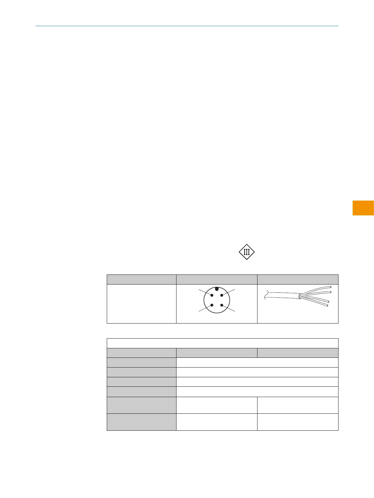
Explanation of the connection terminology used in the following tables:
•
BN = brown
•
WH = white
•
BU = blue
•
BK = black
•
Q = digital output
•
Q
L1
/C = digital output, IO-Link
•
L+ = supply voltage (U
B
)
•
M = ground
DC: 10 ... 30V DC, see "Technical data", page 39
Table 1: Electrical connection
Wxx12L- x4 xH
1 = BN
2 = WH
3 = BU
4 = BK
0.14mm
2
AWG26
Table 2: DC
WTF12L/WTF12V-xxXXXxxxA00
Push-pull 161 162
1 = BN + (L+)
2 = WH MF
3 = BU - (M)
4 = BK Q
L1
/C
De-
fault: MF
Q
Q
De-
fault: Q
L1
(C)
Q
Q
OPERATING INSTRUCTIONS
8027710/2022-04-12 | SICK O P E R A T I N G I N S T R U C T I O N S | WTF12L/WTF12V
31
Subject to change without notice
en