2 Safety information
Connection, mounting and configuration of the product must only be car‐
ried out by qualified personnel.
This product does not constitute a safety component as defined in the
Machinery Directive.
Do not install the product in places exposed to direct UV radiation (sun‐
light) or other weather conditions.
The product must be adequately protected against moisture and contami‐
nation.
2.1 Correct use
The WT34 is an opto-electronic photoelectric proximity sensor (referred to as "sensor"
in the following) for the optical, non-contact detection of objects, animals, and persons.
If the product is used for any other purpose or modified in any way, any warranty claim
against SICK AG shall become void.
3 Product description
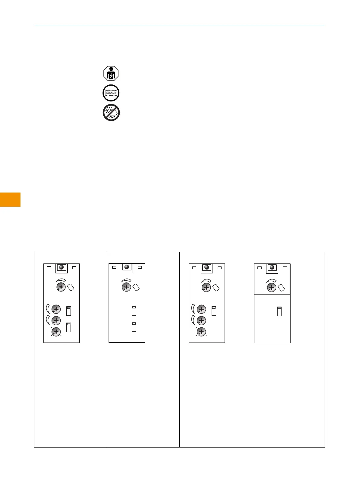
3.1 Operating elements and status indicators
Photoelectric proximity sensor with background suppression.
Table 1: Display and operating elements
t
2
t
2
t
1
t
1
t
1
+ t
2
t
0
PNP
NPN
D
H
1
2
3
6
4
5
7
1.0
1
Yellow LED indicator
2
Potentiometer: adjust‐
ment of the sensing
range
3
Switch: light (L) / dark
(D)
4
Switch: NPN / PNP
5
Potentiometer: adjust‐
ment of time delay t
2
6
Potentiometer: adjust‐
ment of time delay t
1
7
Potentiometer: adjust‐
ment of time stage
1
Yellow LED indicator
2
Potentiometer: adjust‐
ment of the sensing
range
3
Switch: light (L) / dark
(D)
4
Switch: NPN / PNP
t
2
t
2
t
1
t
1
t
1
+ t
2
t
0
D
H
1.0
1
2
3
5
4
6
1
Yellow LED indicator
2
Potentiometer: adjust‐
ment of the sensing
range
3
Switch: light (L) / dark
(D)
4
Potentiometer: adjust‐
ment of time delay t
2
5
Potentiometer: adjust‐
ment of time delay t
1
6
Potentiometer: adjust‐
ment of time stage
1
Yellow LED indicator
2
Potentiometer: adjust‐
ment of the sensing
range
3
Switch: light (L) / dark
(D)
OPERATING INSTRUCTIONS
24
O P E R A T I N G I N S T R U C T I O N S | WT34 8009202.1DM8/2022-09-05 | SICK
Subject to change without notice
en