3 Sensing range setting
Sensor with potentiometer: open the sensor cover and protective hood, make sure that no
dirt has gotten into the device.
The sensing range is adjusted with the potentiometer (type: without stop ). Clockwise
rotation: sensing range increased; counterclockwise rotation: sensing range reduced. We
recommend placing the object within the sensing range, e.g. see table 8. Once the sensing
range has been adjusted, the object is removed from the path of the beam, which causes
the background to be suppressed and the switching output to change [see figure 5 and
figure 6].
Table 8: Sensing range setting
The sensor is adjusted and ready for operation.
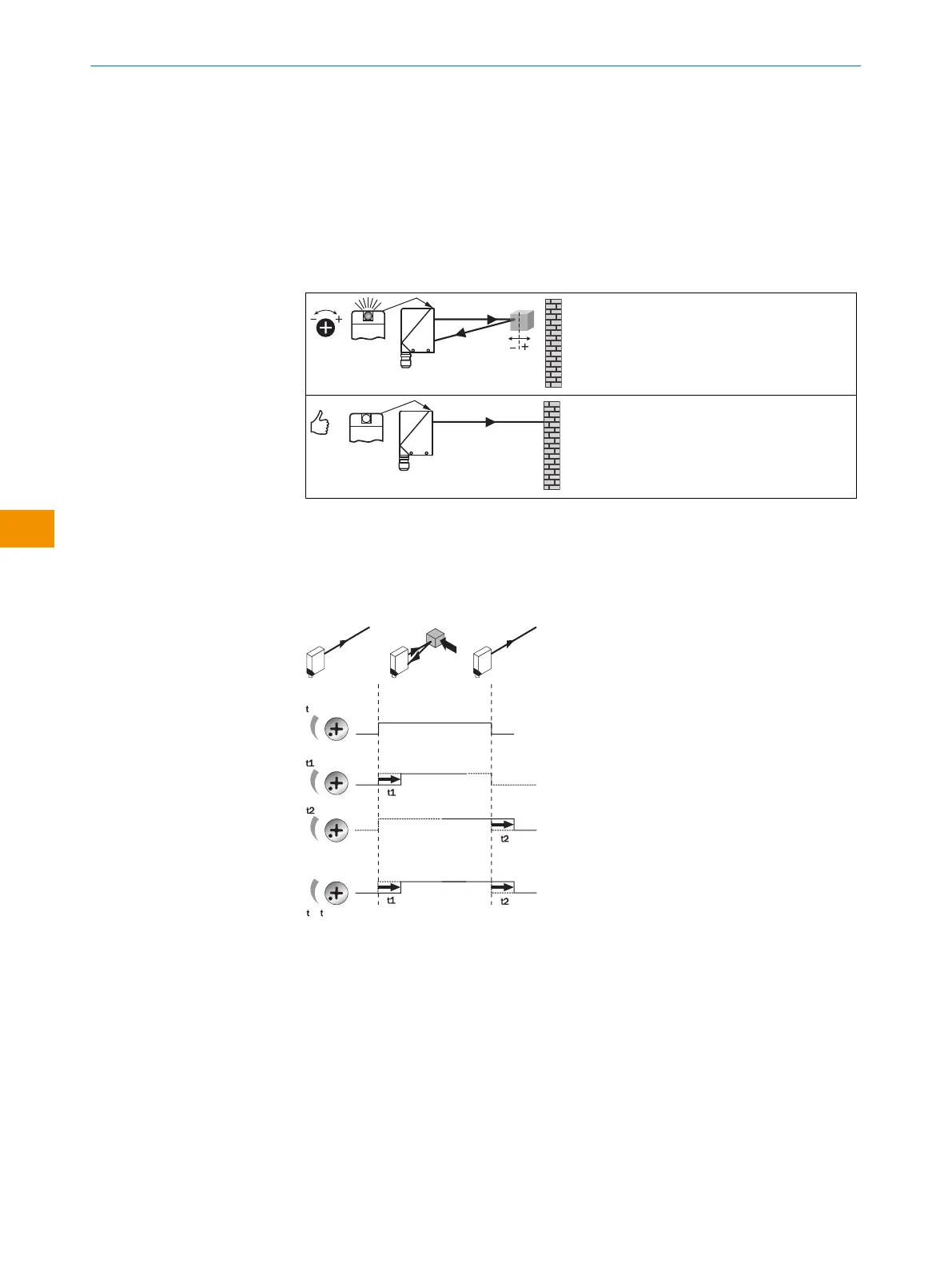
4 Time function setting
WT34: no time delay, t1 = time delay, t2 = time delay; for -R: 0 = relay deactivated, 1 =
relay active. Time delay selector switch can be set on the device according to the following
graphic.
Time stages: 0.5 ... 10s can be adjusted.
0
1 2
+
0.5 ... 10 sec.
0.5 ... 10 sec.
0.5 ... 10 sec.
Figure 7: Time functions
8 Devices with special features
WT34-V210S01, WT34-R210S02: preset to dark switching
WT34-B400S04: preset to light switching, light spot size approx. Ø 15mm (1m)
WT34-R210S06: close range blanking (no detection between 0 and 80mm)
WT34-R220S07: black cover between sender and receiver
OPERATING INSTRUCTIONS
32
O P E R A T I N G I N S T R U C T I O N S | WT34 8009202.1DM8/2022-09-05 | SICK
Subject to change without notice
en