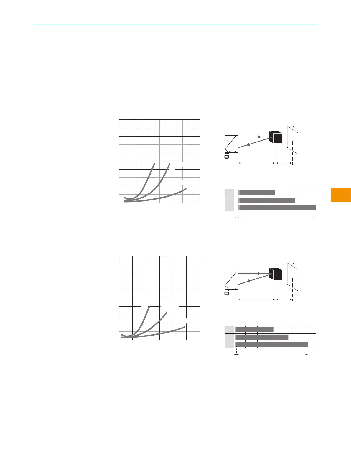
2 Sensing range
WT34are photoelectric proximity sensors with background suppression. Depending on the
remission of the object to be detected, and perhaps the background behind it, a minimum
distance (y) between the set sensing range (x) and the background should be maintained.
Remission: 6% = black 1, 18% = gray 2, 90% = white 3 (referring to standard white as
per DIN5033). We recommend that the adjustment be performed with an object of low
remission.
The minimum distance (= y) for the background suppression can be determined from the
diagram [figure 5 1] as follows:
Example: x = 600 mm, y = 4.5 => 4.5% of 600 mm = 27 mm. That is, the background is
suppressed at a distance of > 627mm from the sensor.
10
8
6
4
2
0
6%/90%
18%/90%
90%/90%
mm 200 400 600 800 1000 1200 1400
Distance in mm
1
2
3
y
x
Figure 5: WT34-Xx4x, -Xx5x, red light
yx
white back-
ground (90%)
x = 600mm, y = 27mm
(= 4.5% of 600mm)
100 600
100 900
100 1,200
1
2
3
A B
A = Detection distance (depending on
object remission)
B= Adjustment range
10
8
6
4
2
0
6%/90%
18%/90%
90%/90%
mm 500 1000 1500 2000 2500 3000
Distance in mm
1
2
3
y
x
Figure 6: WT34-Xx1x, -Xx2x, infrared
light
yx
white back-
ground (90%)
x = 1,000mm, y = 30mm
(= 3% of 1,000mm)
100 1,300
100 1,800
100 2,500
1
2
3
A B
A = Detection distance (depending on
object remission)
B= Adjustment range
OPERATING INSTRUCTIONS
8009202.1DM8/2022-09-05 | SICK O P E R A T I N G I N S T R U C T I O N S | WT34
31
Subject to change without notice
en