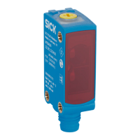
Table 9: Display behavior, case 1
Object detected in near switching
point Q1
Digital output 1 is indicated by
the yellow LED and also by blue
LED 3.
Object detected in far switching
point Q2
Digital output 2 is indicated by
the yellow LED and also by blue
LED 3 + 5.
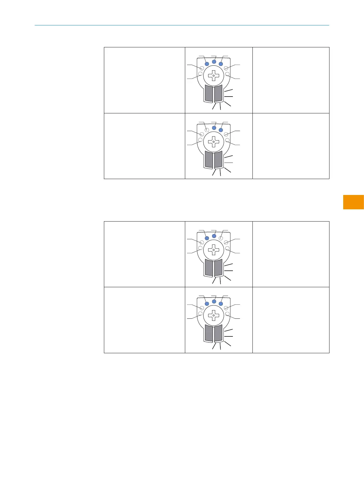
Case 2:
Q1 = far switching point (taught in first) - LED 3
Q2 = near switching point (taught in last) - LED 5
Table 10: Display behavior, case 2
Object detected in far switching
point Q1
Digital output 1 is indicated by
the yellow LED and also by blue
LED 3 + 5.
Object detected in near switching
point Q2
Digital output 2 is indicated by
the yellow LED and also by blue
LED 5.
Please refer to the enclosed “IO-Link photoelectric sensors” operating instructions for
information about adjusting the IO-Link sensing range.
OPERATING INSTRUCTIONS
8028212/2023/10/20 | SICK O P E R A T I N G I N S T R U C T I O N S | WTM4S
57
Subject to change without notice
en