Digital output
WTM4S
Output current I
max.
≤ 100 mA
Circuit protection A, B, C
1)
Response time ≤500µs (MultiMode 1, 2, 3)
2)
≤1,000µs (MultiMode 4, 5)
2)
≤15ms (MultiMode 1 + 6)
2)
Repeatability (response time) 150µs (MultiMode 1, 2, 3)
3)
350µs (MultiMode 4, 5)
3)
5ms (MultiMode 1 + 6
3)
Switching frequency 1,000Hz (MultiMode 1, 2, 3)
4)
500Hz (MultiMode 4, 5)
4)
30Hz (MultiMode 1 + 6)
4)
1)
A = U
B
-connections reverse polarity protected
B = inputs and output reverse-polarity protected
C = Interference suppression
2)
Signal transit time with resistive load
3)
Valid for Q\ on Pin2, if configured via software
4)
With light / dark ratio 1:1
Mechanical data
WTM4S
Enclosure rating IP69K
Ambient temperature, operation -20C…+55 °C
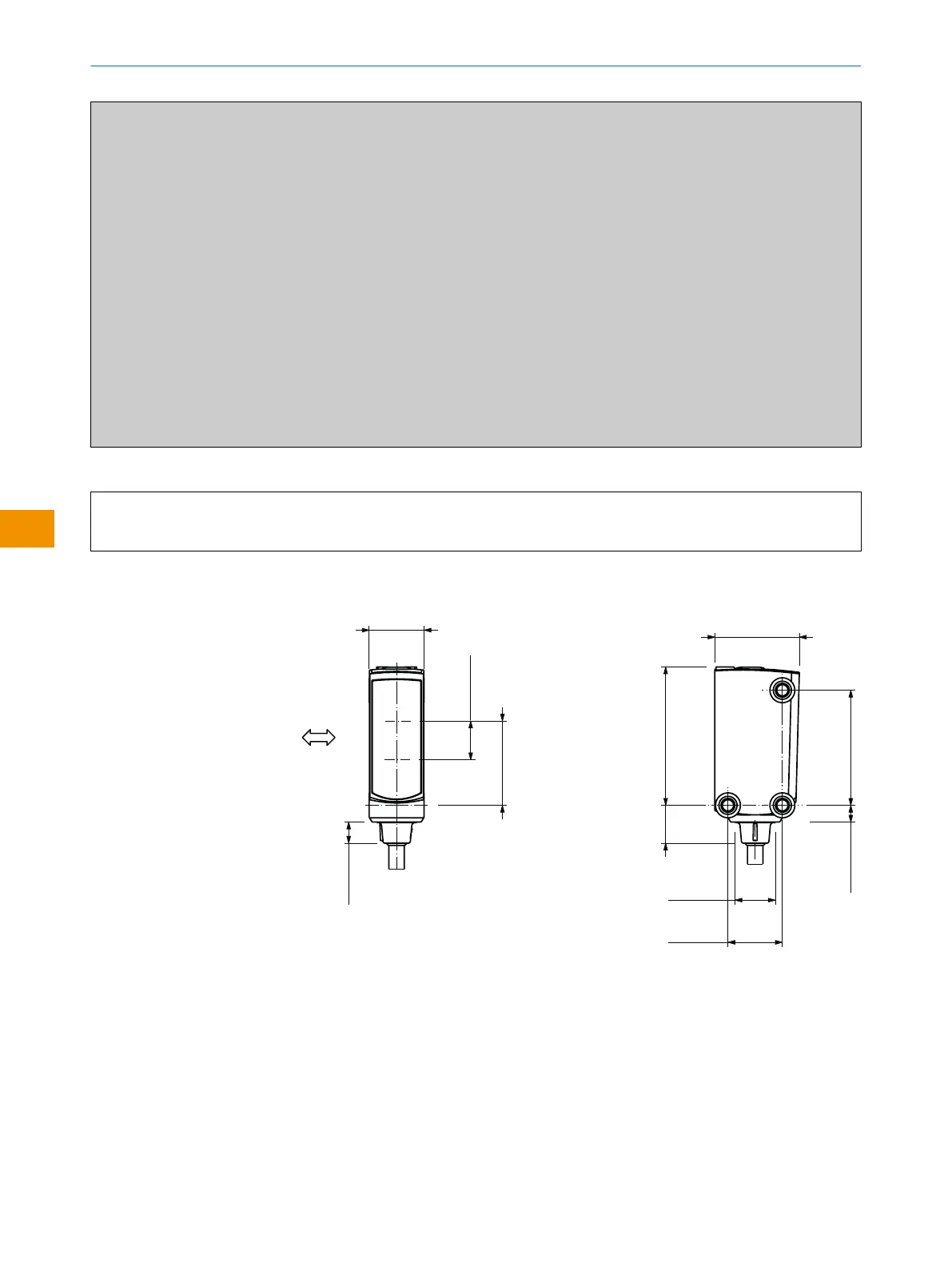
11.2 Dimensional drawings
3
1
2
4
6
12.1 (0.48)
18.6 (0.73)
8.6 (0.34)
5
5
5
18.6 (0.73)
4.7 (0.18)
30.5 (1.2)
8.4 (0.33)
25.4 (1)
3.7 (0.15)
12 (0.47)
8.9 (0.35)
Figure 13: WTx4SP, cable connection
1
Preferred direction of the target object
2
Center of optical axis, receiver
3
Center of optical axis, sender
4
Connection
5
M3 threaded mounting hole
6
Display and setting elements
OPERATING INSTRUCTIONS
62
O P E R A T I N G I N S T R U C T I O N S | WTM4S 8028212/2023/10/20 | SICK
Subject to change without notice
en