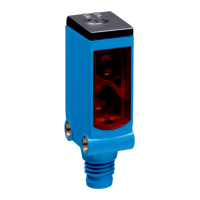
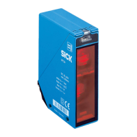
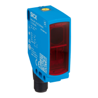
3.3 Electronics
The sensors must be connected in a voltage-free state (U
V
= 0 V
). T
he information in
the graphics [B] must be observed, depending on the connection type:
– Male connector connection: pin assignment
– Cable: wire color
+(L+)
–(M)
Q
a
Q1
MF
in
brn
wht
blk
gra
blu
Figure: B: WTT190L-A15x2B
+(L+)
–(M)
Q
a
Q1
MF
in
brn
wht
blk
gra
blu
1
2
3
4
5
Figure: B-2: -A35x2
Q1/MF
in
4
+(L+)
–(M)
Q
a
brn
wht
blk
blu
1
2
3
Figure: B-3: -A22x2
Only apply voltage/switch on the voltage supply (U
V
> 0 V
) onc
e all electrical connec‐
tions have been established. The green LED indicator lights up on the sensor.
Explanations of the connection diagram (Graphic B):
MF
in
= multifunctional, programmable input
3.4 Functioning of the programmable input
Value Notes
PNP mode Deactivated < 5.0 V Also deactivated when not connected
Active > 10.0 V Max. applied voltage not higher than
UV
NP
N mode Deactivated > 10.0 V Max. applied voltage not higher than
UV
A
ctive < 4.0 V Also active when not connected
The programmable input must be active for the durations specified below (e.g., U
> 10.0 V in PNP mode ) in or
der to set the corresponding functions. For a description of
the available functions and how to select them via the menu, see "Setting the analog
output, switching output, and other sensor configurations via the menu", page 9
Function Minimum duration Maximum duration
Laser shutdown 4 ms -
External teach-in Q1 4 ms -
3.5 Alignment
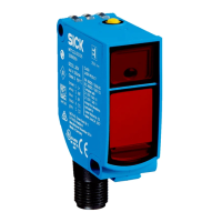
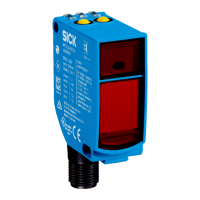
Align the sensor with the object. Select the position so that the red emitted light beam
hits t
he center of the object. You must ensure that the optical opening (front screen) of
the sensor is completely clear [F]. We recommend making the adjustments using an
object with a low remission.
COMMISSIONING 3
8020032.17U4 | SICK
Subjec
t to change without notice
7
 Loading...

