4 Installation
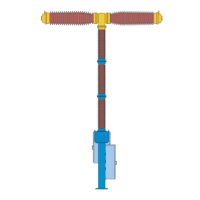
VD Packaging cap for insulator column
1.3 Bracket
1.4 Connecting plate
1.5 Lifting eye plate
1.6 Wooden beam
1.8 Lifting eye-bolt
Fig. 27 Insulator column kit
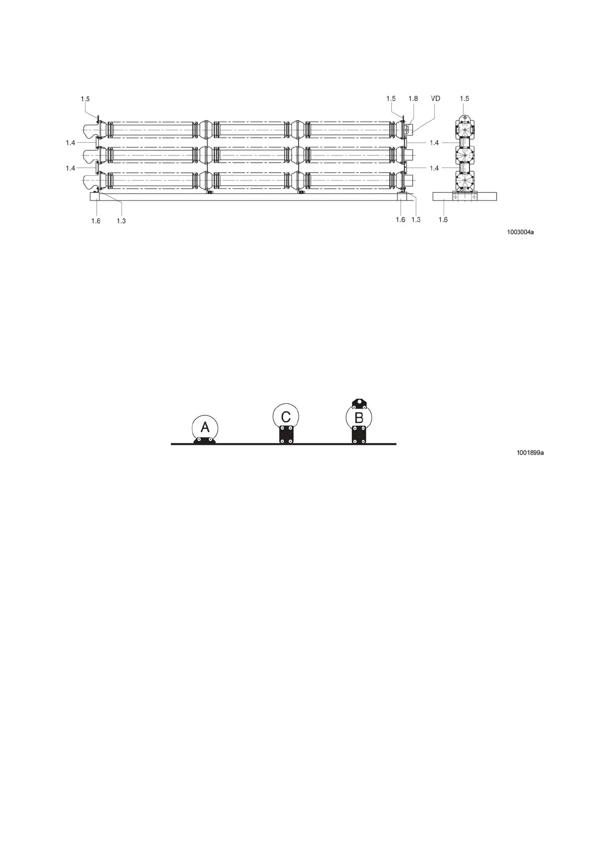
Disassemble the insulator column kit as shown in Fig. 27 starting at the bottom and put the individual columns
down on a solid base. Put the insulator columns down on the connecting plates or a wooden base (rest on the
metal flange, not on the porcelain parts).
Fig. 28 Separating the insulator columns
4.5.4.1 Fixing the Reinforcing Sheets
To fit the reinforcing sheets 1 and 2 in the breaker base, replace the four M 16x80 screws shown in Fig. 29 and
the three M16x55 screws on all three pole columns with the seven M16x10 screws supplied in the accessory
pack.
) Note
When replacing the screws to fit the reinforcing sheets 1 and 2, make sure that the screws are
individually loosened, replaced and tightened again.
50