Operating mode DI
3.3 Interrupts/diagnostics alarms
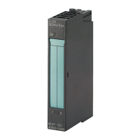
Digital input module DI 8x24VDC HS (6ES7131‑6BF00‑0DA0)
24 Manual, 03/2015, A5E35243810-AA
Meaning of the LED displays
The following tables show the meaning of the status and error displays. Remedial measures
for dealing with diagnostic interrupts can be found in the section Diagnostics alarms
(Page 27).
Table 3- 2 DIAG LED fault/error display
Backplane bus supply of the ET 200SP not OK
Module parameters not assigned
Module parameters assigned and no module diagnostics
Module parameters assigned and module diagnostics
Table 3- 3 Status display of the channel status LED
Process signal = 0
Process signal = 1
Table 3- 4 Status display of the CNT LED
Counting operating mode disabled
Counting operating mode enabled

 Loading...


