Oversampling (OVS) operating mode
5.2 Parameters/address space
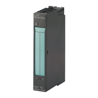
Digital input module DI 8x24VDC HS (6ES7131‑6BF00‑0DA0)
52 Manual, 03/2015, A5E35243810-AA
The figure below shows the chronological sequence for oversampling. The detected input
data of a data cycle (send clock) is copied to the interface module in the next cycle data and
are available to the CPU in the data cycle after the next one.
Detected value from cycle n
Sub-
8 bits apiece x 32 (max.) = max. 32 bytes of input data per data cycle
Figure 5-4 Oversampling
Note
Do not use a reduction ratio for the send clock in this
operating mode for blocks in your user
program (for example, OB61). This will ensure that the processing of the data in the CPU's
user program occurs in chronological coordination with the detection on the module.

 Loading...


