Operating mode DI
3.3 Interrupts/diagnostics alarms
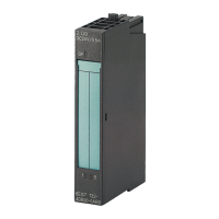
Digital input module DI 8x24VDC HS (6ES7131‑6BF00‑0DA0)
26 Manual, 03/2015, A5E35243810-AA
The digital input module DI 8×24VDC HS supports hardware and diagnostic interrupts.
The module generates a diagnostic interrupt at the following events:
● Channel temporarily unavailable
● Short-circuit
● Parameter assignment error
● No load voltage
● Hardware interrupt lost
Evaluating hardware interrupts with IO controller
The module generates a hardware interrupt at the following events:
● At rising edge (signal change from 0 to 1)
● At falling edge (signal change from 1 to 0)
In the event of an interrupt, interrupt OBs are automatically executed in the CPU of the
IO controller.
You can obtain detailed information on the event in the hardware interrupt organization block
with the instruction "RALARM" (read additional interrupt info) and in the STEP 7 online help.
The channel of the module that triggered the hardware interrupt is entered in the start
information of OB40 in the OB40_POINT_ADDR tag. The following figure shows the
assignment to the bits of double word 8 in local data.
Figure 3-6 OB40_POINT_ADDR tag

 Loading...


