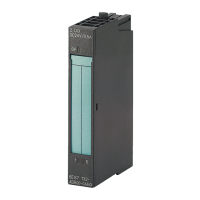
Digital input module DI 8x24VDC HS (6ES7131‑6BF00‑0DA0)
28 Manual, 03/2015, A5E35243810-AA
Counting operating mode (CNT)
Wiring and block diagrams
This section contains the block diagram for the DI 8×24VDC HS module with the pin
assignments for 1, 2 and 3-wire connection in counting operating mode. You may use and
combine the different wiring options for all channels.
Information on wiring the BaseUnit can be found in the system manual ET 200SP Distributed
I/O System (http://support.automation.siemens.com/WW/view/en/58649293).
Note
The module's load group must start with a light BaseUnit.
Keep this in mind also during the

 Loading...


