Do you have a question about the Siemens 7ML5670 and is the answer not in the manual?
Explains safety symbols used in the manual and on the product for hazard identification.
Provides an introduction to the manual's content and structure.
Lists various industries and processes where the SITRANS LC300 is utilized.
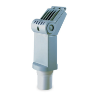
Details the main technical and functional characteristics of the SITRANS LC300.
Discusses factors for choosing an appropriate installation site for the device.
Provides critical warnings for safe handling to prevent damage to the SITRANS LC300.
Details the steps and safety instructions for securely mounting the SITRANS LC300.
Highlights important considerations and potential issues during the installation phase.
Explains the device's power supply circuit and signal output characteristics.
Step-by-step guide for wiring the SITRANS LC300 to the current loop.
Covers specific wiring configurations for installations in hazardous locations.
Provides guidelines for safe installation in environments with specific safety requirements.
Guides users through powering on and basic interface setup of the SITRANS LC300.
Explains the device's menu structure, rotary switch, and button operations.
Details how to view the primary variable (PV) in picoFarads (pF).
Describes the process for adjusting the Lower Range Value (LRV).
Explains how to set and adjust the Upper Range Value (URV).
Covers setting fault protection and viewing analog signal information.
Information on device diagnostics, fault values, and error handling.
Guides on adjusting the damping value for signal smoothing.
Procedures for recommissioning the device and its maintenance requirements.
Guidelines for device repair and limitations of liability.
Details electrical supply requirements and environmental operating conditions.
Covers measurement accuracy, stability, safety features, and diagnostics.
Information on current loop output and device display/controls.
Specifies probe types, process connections, and materials in contact with the medium.
Details device weight, pressure/temperature limits, and product certifications.
Diagram illustrating the SITRANS LC300 with key measurement points and component labels.
Specific dimensions for the threaded rod version with PFA probe.
Dimensions for the threaded rod version including a stilling well.
Details for the non-insulated threaded cable probe.
Dimensions for the insulated threaded cable probe.
Dimensions for the non-insulated welded flange cable probe.
Dimensions for the insulated welded flange cable probe.
Information on cable strength limits and procedures for shortening the cable.
Important warnings and notes for installation and handling of the device.
Operating curves showing permissible pressure and temperature limits for various configurations.
Guidance on finding manuals, certificates, and downloads via online portals.
Details on how to obtain technical assistance and contact Siemens support.
| Brand | Siemens |
|---|---|
| Model | 7ML5670 |
| Category | Transmitter |
| Language | English |