21 / 50
Siemens Actuators SAS.., SAT.. for valves CE1P4041en
Building Technologies Handling 2015-05-19
Connection terminals Stroke actuator Rotary actuator
Control path
valve AàAB
Bypass valve
B à AB
Position
feedback U
Y
6 V
13.6 mA
Actuator’s stem
extends (60%)
Actuator’s spindle turns in
clockwise direction (60 %)
Opening Closing 6 V
Y
5 V
12 mA
Actuator’s stem
retracts (50%)
Actuator’s spindle turns in
counterclockwise
direction (50 %)
Closing Opening 5 V
Z connected to G
Actuator’s stem
extends
Actuator’s spindle turns in
clockwise direction
Opening Closing 10 V
Z connected to G0
Actuator’s stem
retracts
Actuator’s spindle turns in
counterclockwise
direction
Closing Opening 0 V
Only SAS61.33, SAS61.33U,
SAS61.53, SAT61.51
No voltage at G and G0
(fail safe function)
1)
Actuator’s stem
retracts (until end
position is
reached)
- Closing Opening -
1)
Closing action is always completed first, also when power returns.
Make the function check for 3-position actuators according to the following table:
Connection terminals Stroke actuator Rotary actuator
Control path
valve AàAB
Bypass valve
B à AB
Voltage at Y1 Actuator’s stem extends
Actuator’s spindle turns in
clockwise direction
Opening Closing
Voltage at Y2 Actuator’s stem retracts
Actuator’s spindle turns in
counterclockwise direction
Closing Opening
No voltage at Y1 and Y2
Actuator’s stem maintains
the position
Actuator’s spindle maintains
the position
Maintains the position
Only SAS31.50, SAS31.53,
SAS81.33, SAS81.33U, SAT31.51
No voltage at G and G0
(fail safe function)
1)
Actuator’s stem retracts (until
end position is reached)
- Closing Opening
1)
Closing action is always completed first, also when power returns.
· Observe information given in chapter 4.2.1 Positioning signal and flow
characteristic selection, page 26.
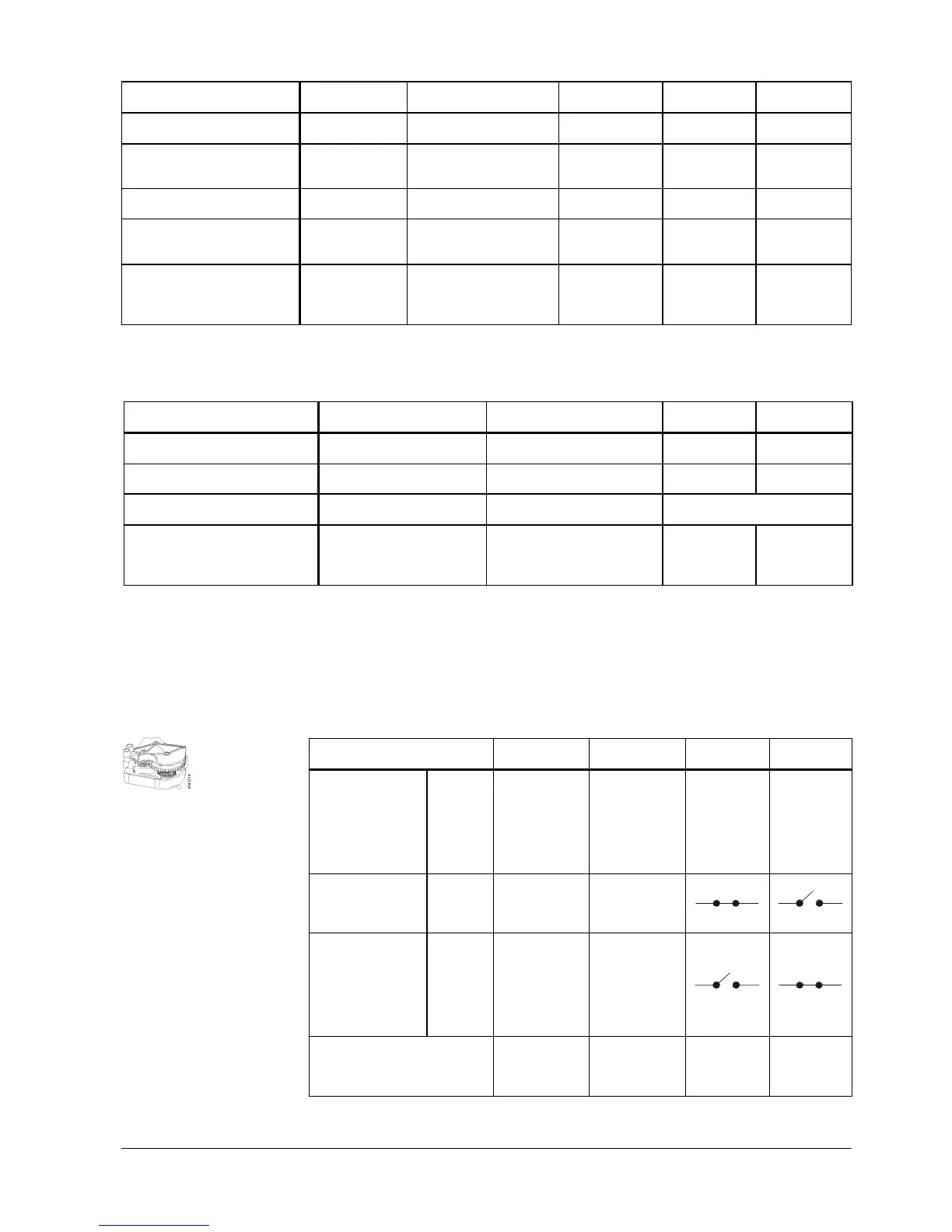
Make the function check of the mounted auxiliary switch with a point test according
to the following table – example switching point at 25% position:
Connection terminals
Stroke
actuator
Rotary
actuator
Terminal
S1 – S3
Terminal
S1 – S2
Voltage at Y2
Y = 0 V
Actuator’s
stem retracts
(until end
position is
reached)
Actuator’s
spindle turns in
counter-
clockwise
direction (until
end position is
reached)
- -
No voltage at Y1
und Y2
Y = 0 V
Actuator’s
stem maintains
the position
Actuator’s
spindle
maintains the
position
Voltage at Y1 for
desired valve
position % + 2% x
positioning time
Example:
SAS31.00 = 27 % x
120 sec = 32.5 sec
Valve
position
% + 2%
Y = 2.7 V
Actuator’s
stem extends
to desired
position (27%)
Actuator’s
spindle turns in
clockwise
direction to
desired
position (27%)
Check switching point with
voltmeter
Actuator’s
stem maintains
the position
Actuator’s
spindle
maintains the
position
- -
SA..31.. and SA..81..
Note
Auxiliary switch
ASC10.51

 Loading...