25 / 50
Siemens Actuators SAS.., SAT.. for valves CE1P4041en
Building Technologies Functions and control 2015-05-19
4.2 Modulating control
The modulating positioning signal
drives the actuator steplessly. The
positioning signal range
(DC 0...10 V / DC 4...20 mA /
0...1000 Ω) corresponds in a linear
manner to the positioning range (fully
closed...fully open, or 0…100 %
stroke).
The actuator is controlled via terminal
Y or forced control Z (page 30). The
desired stroke / the desired rotation is
transferred to the valve stem / the
valve spindle.
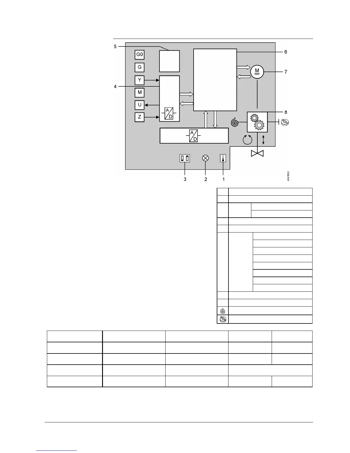
1Calibration slot
2LED (2 colors)
3
DIL
switches
Changeover of characteristic
Positioning signal
4A/D conversion
5Power supply
6
Control
functions
Identification of seat
Position control
Motor control
Detection of foreign bodies
Calibration
Forced control
Characteristics function
Manual adjustment
7Brushless DC motor
8Gear train
Fail safe function
Manual adjuster
Positioning signal Stroke actuator Rotary actuator
Control path valve
AàAB
Bypass valve
B à AB
Signal Y, Z increasing Actuator’s stem extends
Actuator’s spindle turns in
clockwise direction
Opening Closing
Signal Y, Z decreasing Actuator’s stem retracts
Actuator’s spindle turns in
counterclockwise direction
Closing Opening
Signal Y, Z constant
Actuator’s stem maintains the
position
Actuator’s spindle maintains
the position
Maintains the position
No voltage at Y1 and Y2;
with fail safe function
Actuator’s stem retracts
Actuator’s spindle turns in
counterclockwise direction
Closing Opening
Observe the information given in chapter 4.2.1 Positioning signal and flow
characteristic selection on page 26.
Note

 Loading...