Siemens AG SPR2-310.815.01.07.02 ARCADIS Varic
12.06 CS PS SP
Final Work Steps 47
Page 47 of 64
Medical Solutions
Tab. 6 Measurement points for the protective conductor resistance measurement
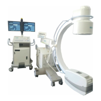
Measuring points
Measurement from the protective conductor connection of the power plug to the:
Base unit, handle attachment screw for I.I. cover
Base unit, one attachment screw at I.I. grid
Base unit, one attachment screw at I.I.
Base unit, one attachment screw at SIREPHOS
Base unit, one screw at cover of horizontal carriage
Base unit, one screw at lifting column cover (rotational brake)
Base unit, one screw at lifting column
Base unit, a lateral screw at brake pedal
Base unit, back cover (electronics box)
Base unit, equipotential bonding connection
Base unit, base plate of electronics box (at unpainted location)
Base unit, one screw at the back of each monitor
Monitor cart, one screw at monitor support
Monitor cart, one screw at the small, top back cover
Monitor cart, one screw at the large, lower back cover
Monitor cart, one screw at back cover of switch-on assembly
Monitor cart, one screw at the front cover
Monitor cart, one screw at the right side cover
Monitor cart, one screw at the left side cover
Monitor cart, one screw at the right handle
Monitor cart, one screw at the left handle

 Loading...