V1.0
46
ANNEX A
Cable Specifications
1. PC to NGSM(Power Supply)
Depending on the type of serial connector that is used by the PC. The cable layout for both
9pins and 25pin are listed below:
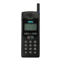
Computer:
Sub-D 25 pins
NGSM:
Sub-D 25 pins
TxD Pin 2 RxD Pin 3
RxD Pin 3 TxD Pin 2
RTS Pin 4 DCD Pin 8
DCD Pin 8 RTS Pin 4
CTS Pin 5 DTR Pin 20
DSR Pin 6 DTR Pin 20
DTR Pin 20 CTS Pin 5
DTR Pin 20 DSR Pin 6
GND Pin 7 GND Pin 7
TABLE A.1 D25 TO D25 CONNECTION
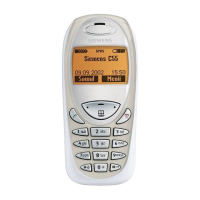
Computer:
Sub-D 9 pins
NGSM:
Sub-D 25 pins
TxD Pin 2 RxD Pin 3
RxD Pin 3 TxD Pin 2
RTS Pin 7 DCD Pin 8
DCD Pin 1 RTS Pin 4
CTS Pin 8 DTR Pin 20
DSR Pin 6 DTR Pin 20
DTR Pin 4 CTS Pin 5
DTR Pin 4 DSR Pin 6
GND Pin 5 GND Pin 7
TABLE A.2 D9 TO D25 CONNECTION
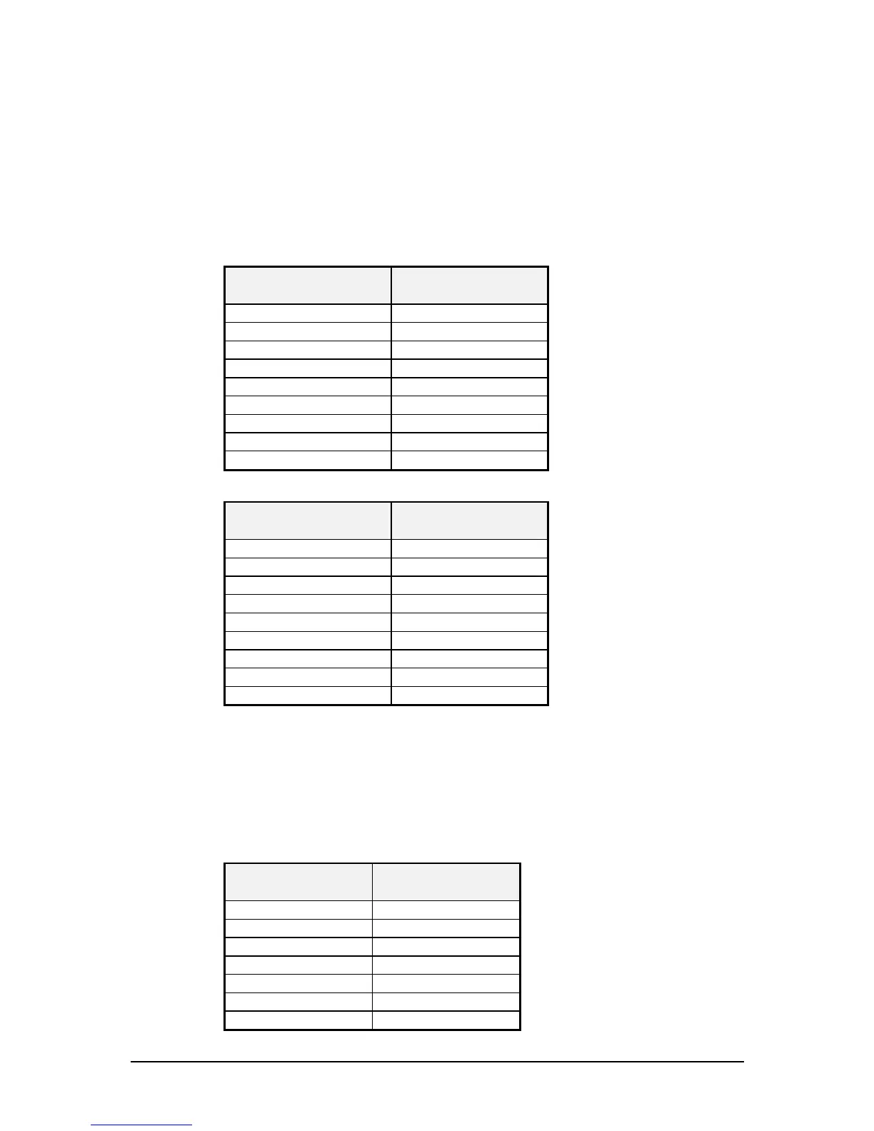
2. PC to CMD 53 or CTS 55
Depending on the type of connector used for the PC serial interface, two different type of
cables can be used:
Computer:
Sub-D 25 pins
CMD / CTS:
Sub-D 9 pins
TxD Pin 2 RxD Pin 2
RxD Pin 3 TxD Pin 3
DSR Pin 6 DTR Pin 4
GND Pin 7 GND Pin 5
DTR Pin 20 DSR Pin 6
CTS Pin 5 RTS Pin 7
RTS Pin 4 CTS Pin 8
TABLE A.3 D25 TO D9 CONNECTION

 Loading...