3.4 Operating and display elements
3.4.1 Front view of the module with BusAdapter
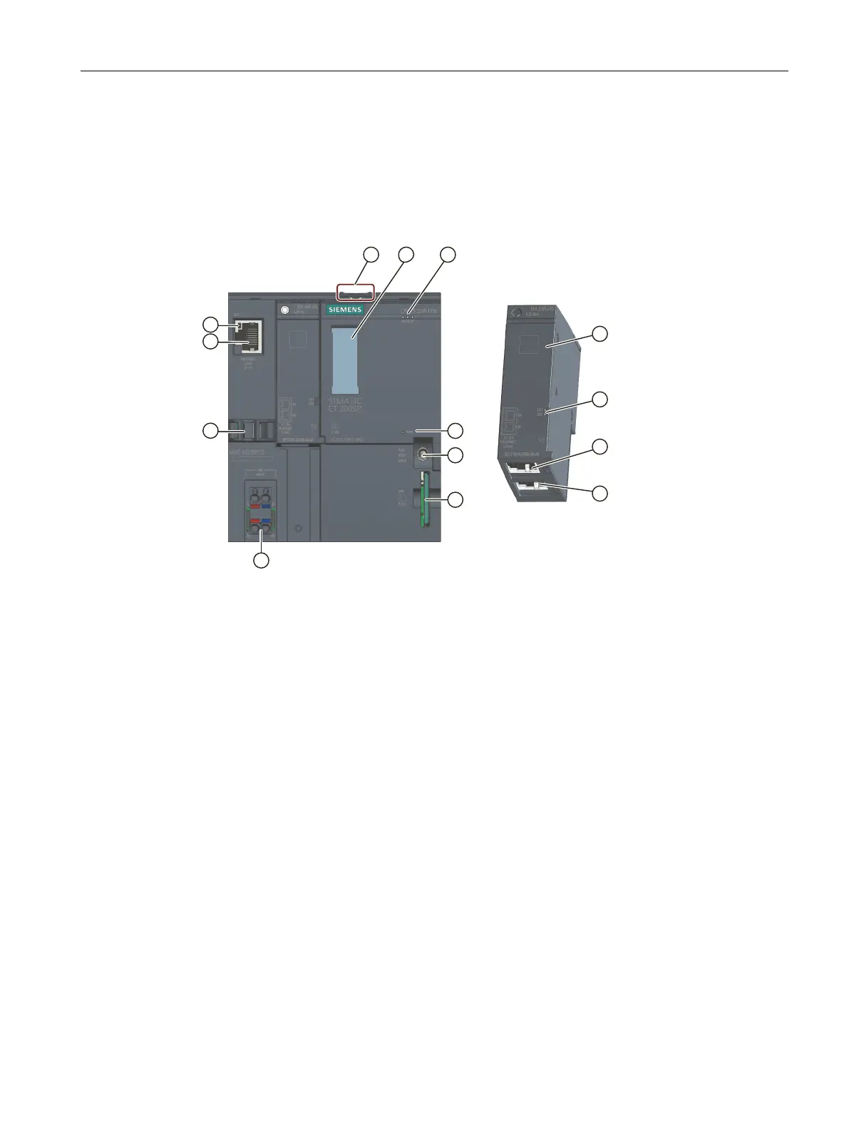
The figure on the left shows the CPU1512SP‑1PN including a plugged BA2xRJ45
BusAdapter. The figure on the right shows a separate view of the BA2xRJ45 BusAdapter.
① Mounting rail release
② Labeling strips
③ LEDs for status and error displays
④ LED for display of the supply voltage
⑤ Mode switch
⑥ Slot for the SIMATIC memory card
⑦ Connection for supply voltage (included in product package)
⑧ Cable support and attachment for port P3 of the PROFINET interface
⑨ LEDs for status displays of the PROFINET interface: LK1 and LK2 on BusAdapter, LK3 on CPU
⑩ Port P3 of the PROFINET interface: RJ45 socket
⑪ Separate view of the BusAdapter
⑫ Port P1R of the PROFINET interface: RJ45 socket on BusAdapter BA2×RJ45
R: Ring port for configuring a ring topology with media redundancy
⑬ Port P2R of the PROFINET interface: RJ45 socket on BusAdapter BA2×RJ45
R: Ring port for configuring a ring topology with media redundancy
Figure 3-2Front view of the CPU1512SP‑1PN with BusAdapter
3.5 Mode switch
Use the mode switch to set the CPU operating mode.
19
Product overview
3.5 Mode switch
CPU 1512SP-1 PN (6ES7512-1DM03-0AB0)
Equipment Manual, 11/2022, A5E33591411-AE
 Loading...