Interrupts, error messages, diagnostics and system
alarms
5
The status and error displays of the CPU1512SP‑1PN are described below.
You will find additional information on "Interrupts" in the STEP7 online help.
You can find additional information on the topics of "Diagnostics" and "System alarms" in the
Diagnostics (https://support.automation.siemens.com/WW/view/en/59192926) function
manual.
5.1 Status and error display of the CPU
LED displays
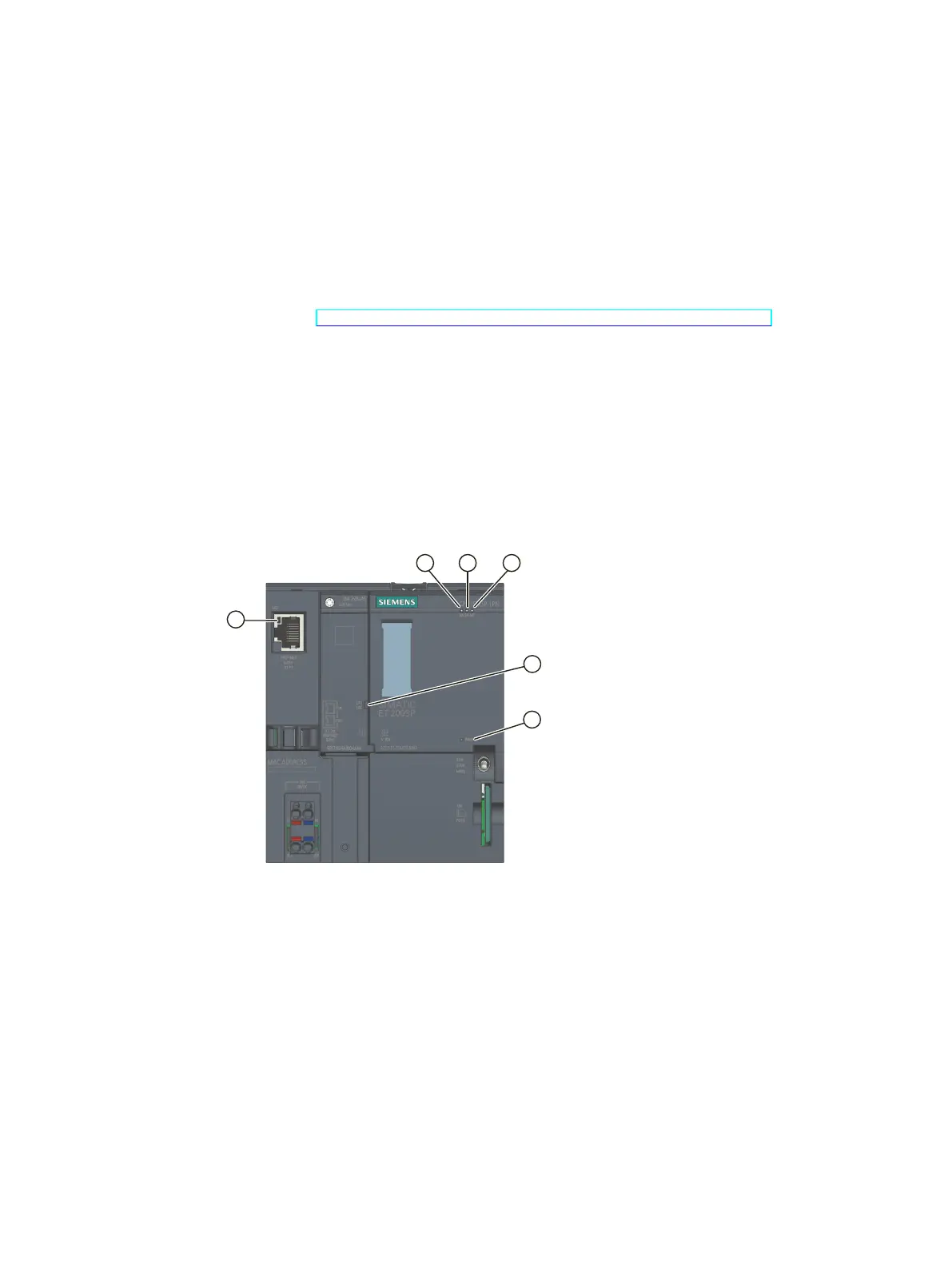
The figure below shows the LED displays of the CPU1512SP‑1PN and the BA2xRJ45
BusAdapter.
① RUN/STOP LED (green/yellow LED)
② ERROR LED (red LED)
③ MAINT LED (yellow LED)
④ LINKRX/TX-LED for the ports X1P1 and X1P2 (green LEDs on the BusAdapter)
⑤ POWER LED (green LED)
⑥ LINK RX/TX LED for port X1P3 (green LED on the CPU)
Figure 5-1LED displays on the CPU and BusAdapter
Meaning of the POWER, RUN/STOP, ERROR and MAINT LEDs
CPU1512SP‑1PN features an LED for monitoring the supply voltage of the electronics (PWR)
and three LEDs for displaying the current operating and diagnostics status. The following
25
CPU 1512SP-1 PN (6ES7512-1DM03-0AB0)
Equipment Manual, 11/2022, A5E33591411-AE
 Loading...