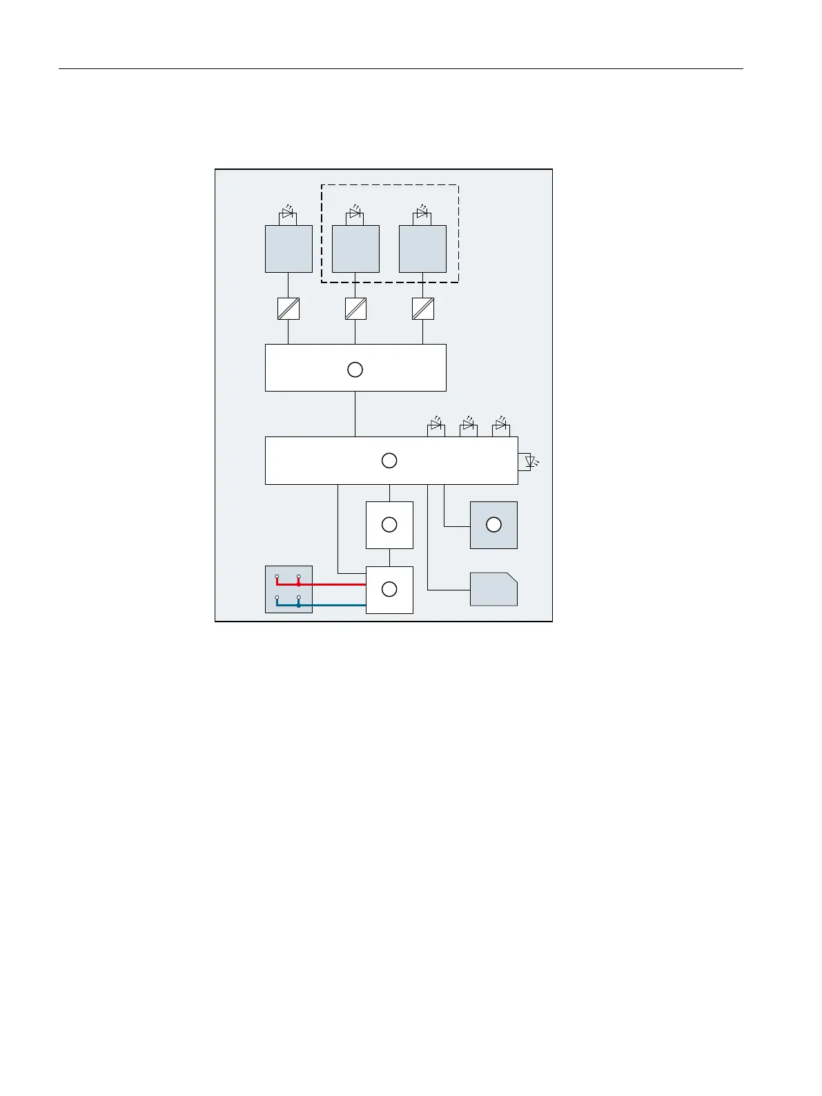
Block diagram
The following figure shows the block diagram of the CPU1512SP‑1PN.
/
;'&9
0
/.
;
;
3
/.
35
/.
56(507
3:5
35
① PROFINET switch P1R PROFINET interface X1 Port 1
② Electronics P2R PROFINET interface X1 Port 2
③ Backplane bus interface P3 PROFINET interface X1 Port 3
④ Internal supply voltage L+ 24 V DC supply voltage
⑤ RUN/STOP/MRES mode selector M Ground
X5 BusAdapter LK1, 2, 3 LED Link TX/RX (green)
X50 SIMATIC memory card R/S RUN/STOP LED (green/yellow)
X80 24VDC Infeed of supply voltage ER ERROR LED (red)
MT MAINT LED (yellow)
PWR POWER LED (green)
Figure 4-1Block diagram of the CPU1512SP‑1PN
24
CPU 1512SP-1 PN (6ES7512-1DM03-0AB0)
Equipment Manual, 11/2022, A5E33591411-AE
Wiring
 Loading...