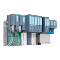
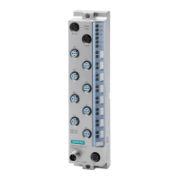
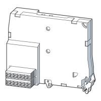
LK1/LK2 LEDs on the BusAdapter
Table 6-6 Status and error displays of the LK1/LK2 LEDs
LED Meaning Remedy
LK1/LK2
Off
There is no Ethernet connection between the PROFI‐
NET IO interface of your PROFINET device and a
communication partner (e.g. IO controller).
Check whether the bus cable to the switch/IO control‐
ler is interrupted.
On
There is an Ethernet connection between the PROFI‐
NET IO interface of your PROFINET device and a
communication partner (e.g. IO controller).
---
Flashes
The "Node flash test" is run (the RN/ER/MTLEDs also
flash).
---
Operating principle
The LED error display provides information on the cause of the error. After notification by the
flash signal, the error type is displayed followed by the error location/error code.
The LED error display
● takes precedence over all other states that are displayed by the ERROR and MAINT LEDs.
● remains switched on until the cause of the error is eliminated
Table 6-7 Display of error type and error location
Sequence Description
1 ER and MT LEDs flash 3x at 0.5 Hz Indication of the error type
2 MT LED flashes at 1 Hz Display of error type (decimal)
3 ER and MT LEDs flash 3x at 2 Hz Indication of error location/error code
4 ER LED flashes at 1 Hz Display of tens digit (decimal) of the error location / error code
5 MT LED flashes at 1 Hz Display of ones digit (decimal) of the error location / error code
6 Repeat steps 1 to 5 until the cause of the error has been eliminated.
Error display
Table 6-8 Error display
Error type
(MAINT)
Cause of error Solution
1
● No server module
● Interruptions on the backplane bus
● Short-circuit on backplane bus
Check the configuration of the
ET 200SP HA.
Displays and interrupts
6.1 Status and error displays
Interface Module IM 155-6 PN HA (6DL1155-6AU00-0PM0)
22 Manual, 05/2017, A5E39262148-AA

 Loading...


