FC2005/FC901 SYSTEM CONNECTION DIAGRAM
FC2005/FC901 SYSTEM CONNECTION DIAGRAM
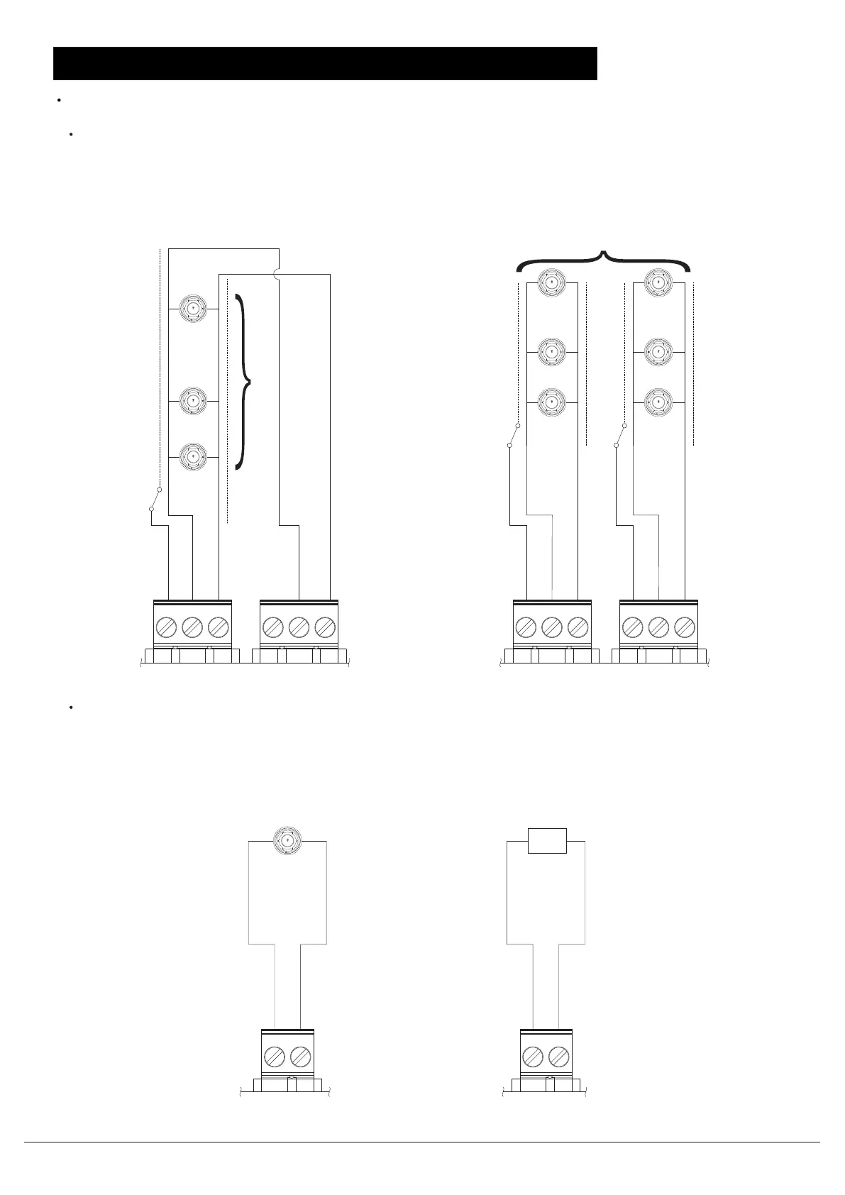
SLC loop connections
Supervised and power limited, detail device compatibility list refer to user manual Appendix B
Auxiliary power
Non supervised and power limited
Class A
...
50 max devices
0.07A@6-32 VDC
Note: The earth gets connected to the
shield (if used)
EARTH
S_BN
S_BP
EARTH
S_AN
S_AP
EARTH
S_BN
S_BP
EARTH
S_AN
S_AP
0.07A@6-32 VDC
50 max devices
...
...
0.07A@6-32 VDC
Class B
Note: The earth gets connected
to the shield (if used)
X2_P
X2_N
X1_P
X1_N
Conventional detectors
Alarm 0.75A @19-28VDC
Normal 0.05A @19-28VDC
Auxiliary power output 2
(Resettable, power limited)
Power -
Power +
Alarm 0.75A @19-28VDC
Normal 0.05A @19-28VDC
Auxiliary power output 1
(Non-resettable, power limited)
+
-
+
-
Max. current= 0.75A
Max. current= 0.75A
24V
applicance
Document ID: A5Q00039713A
Page 9/12 02.2012
Fire Safety & Security Products
Building Technologies
FC2005/FC901 installation instruction

 Loading...