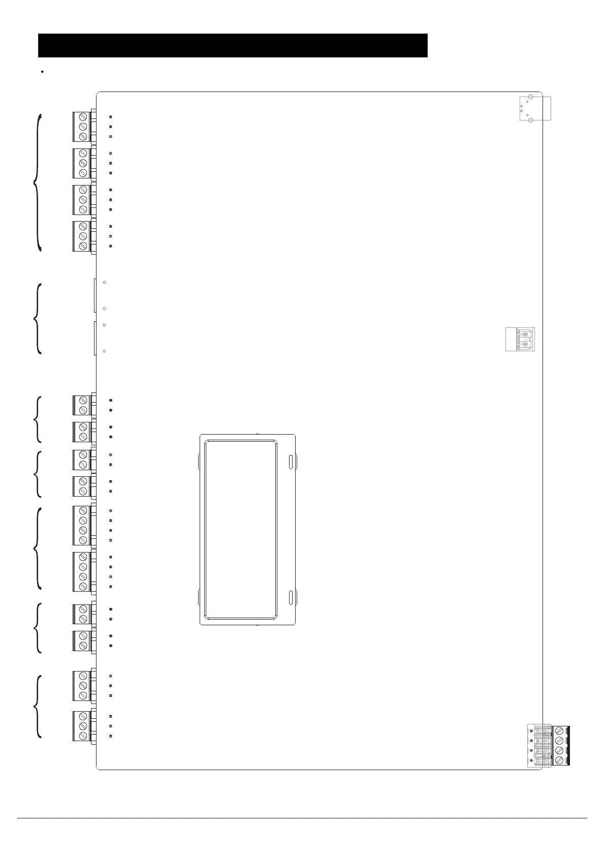
FC2005/FC901 SYSTEM CONNECTION DIAGRAM
FC2005/FC901 SYSTEM CONNECTION DIAGRAM
EARTH
S_BN
S_BP
EARTH
S_AN
S_AP
X2_P
X2_N
X1_P
X1_N
EARTH
SE_B
SE_A
GND1
EARTH
PR_B
PR_A
GND1
CT_P
CT_N
LL_SP
LL_SN
N_BP
N_BN
N_AP
N_AN
DACT
PORT1
DACT
PORT2
S_NO
S_CO
S_NC
U_NO
U_CO
U_NC
A_NO
A_CO
A_NC
T_NC
T_CO
T_NO
Battery connector
12AH - 18AH@24VDC
Supervised, Non power limited
USB type B plug
DC power input
6.5A@26VDC
SLC loop Auxiliary power Series interface circuit
City tie or
lease line
Notification Application
Circuits(NAC)
DACT Relays
Note: All the wiring must be in according with local codes and National Electric Code.
Document ID: A5Q00039713A
Page 8/12 02.2012
Fire Safety & Security Products
Building Technologies
FC2005/FC901 installation instruction

 Loading...