Series Interface Circuit
Power limited
City tie or lease line
power limited
100mA@26VDC Active (19-28VDC on Bat t ery)
Polarity Reversing Circuit
+26VDC Normal (OUTPUT 1 and OUTPUT 2)
-26V DC Alarm (OUTPUT 1)
0V Trouble (OUTPUT 1)
-26V DC Supervisory (OUTPUT 2)
External Circuit Resistance 2K-5K ohms
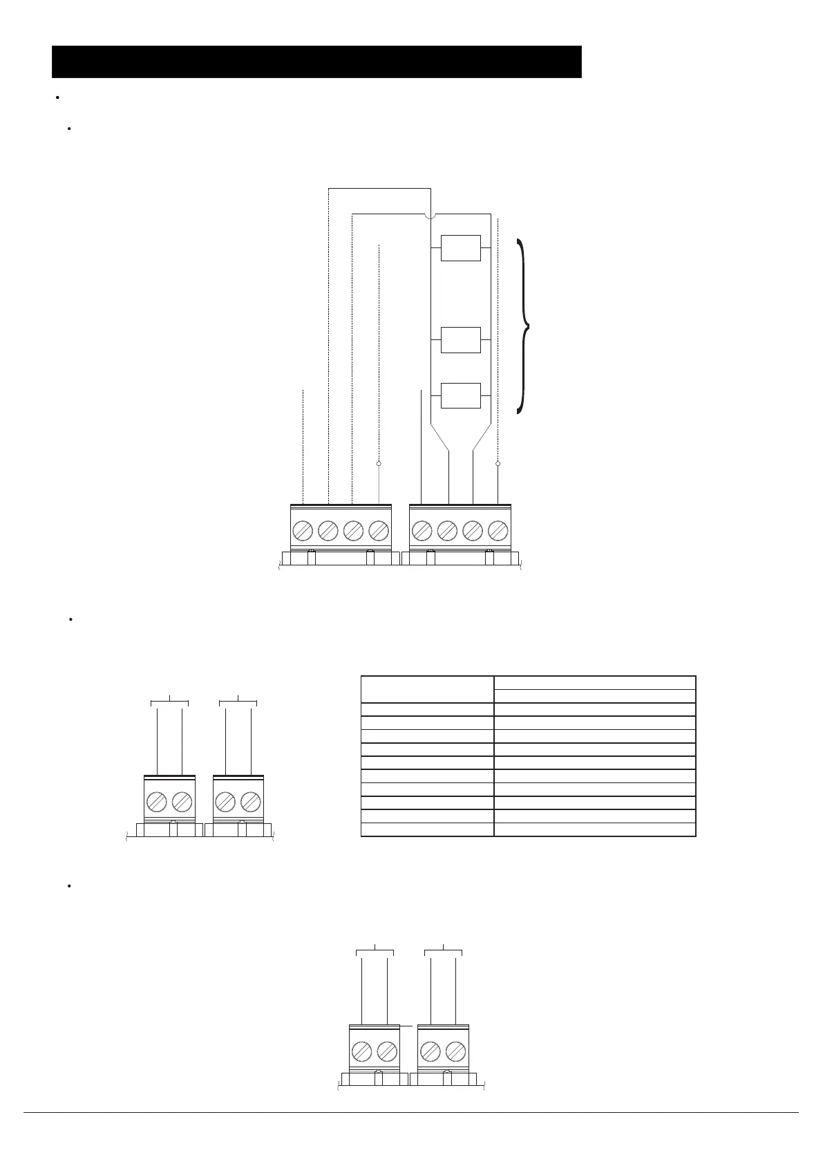
M unicipal Tie Voltage 350mA @26VDC Active(19-28VDC on Bat t ery)
+26VDC Normal & 1mA Supervisory Current
350mA Alarm@+26VDC
M unicipal Tie Trip Coil 14.5 ohms
M unicipal Tie Supervisory Current 1mA
C it y t ie and leased l i ne r at ing
Leased Line V olt age Rating
CT_P
CT_N
LL_SP
LL_SN
Output 2Output 1
Master box
EARTH
SE_B
SE_A
GND1
EARTH
PR_B
PR_A
GND1
8 FSD max
(Reserved)
Connected to shield(if used)
...
FSD
FSD
FSD
Used for Class A wiring
Connected to shield(if used)
(Reserved)
Notification Application Circuits
N_BP
N_BN
N_AP
N_AN
Supervised, power limited, Max. current(NAC A+NAC B)=2.5A
FC2005/FC901 SYSTEM CONNECTION DIAGRAM
FC2005/FC901 SYSTEM CONNECTION DIAGRAM
Document ID: A5Q00039713A
Page 10/12 02.2012
Fire Safety & Security Products
Building Technologies
FC2005/FC901 installation instruction

 Loading...