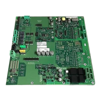
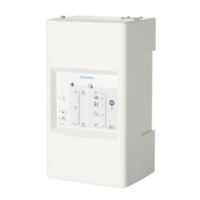
Periphery board (250p) FCI2016
Configuration input power and battery
1
11 |
Building Technologies
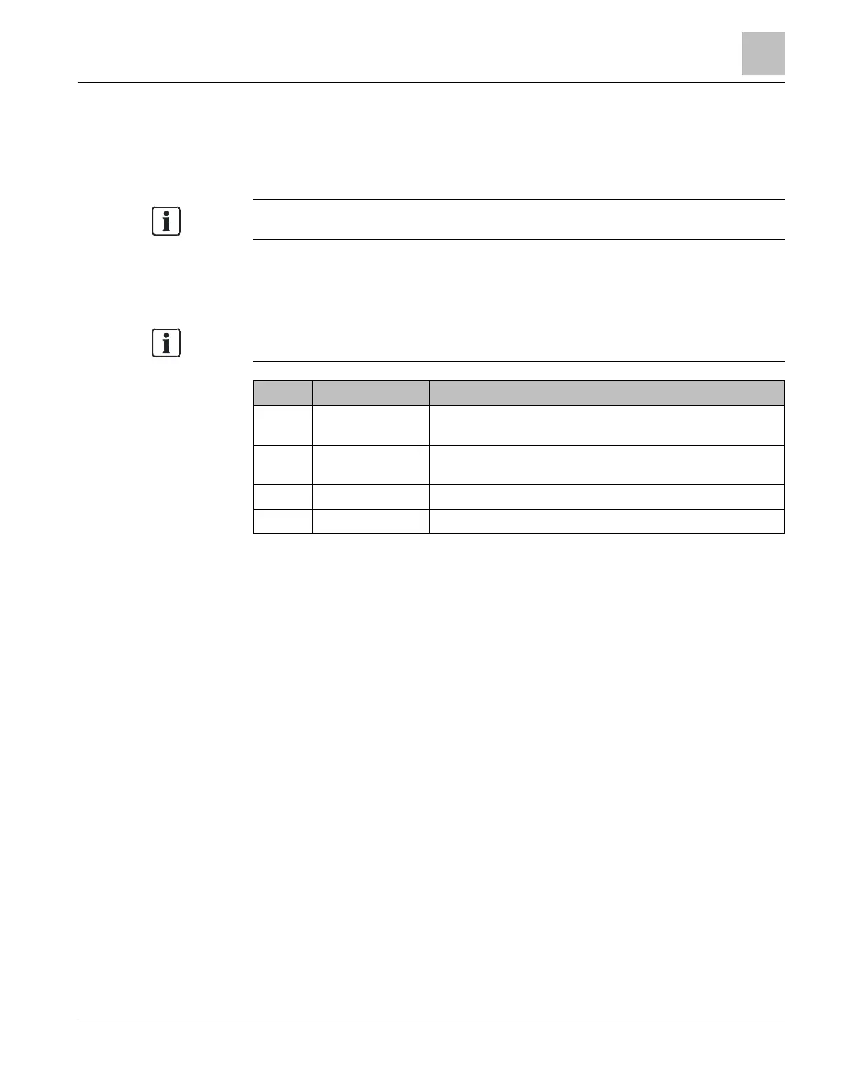
1.4.2 X301 Power supply terminal block 1
Make sure AC is disconnected. Wire power supply (300 W or 170 W) connection to
X301. Check whether jumper X305 is in position 1-2 before a single power supply is
connected.
Terminal X301 must always have a power supply connected.
Do not connect AC or batteries until all jumpers and modules are configured and
connected in the system. Once everything is installed and connected, first AC, then the
batteries must be connected.
To power down the system, first disconnect the batteries and then the line
Pin Designation Description
1 BROO
(White) AC low signal. Signals when the supply system
connection drops below AC 102 V.
2 PSSI
(Green) Power supply status indication. Used by the
periphery board to know the health of the power supply.
3 GND (Black) Return (ground)
4 +24 V (Red) DC +24 V system supply
Admissible cable cross-section: 1 x 12…18 AWG or 2 x 16…18 AWG
 Loading...