Periphery board (250p) FCI2016
circuit driver 1 (circuits 1 and 2)
1
18 | 46
1.8.1 Wiring
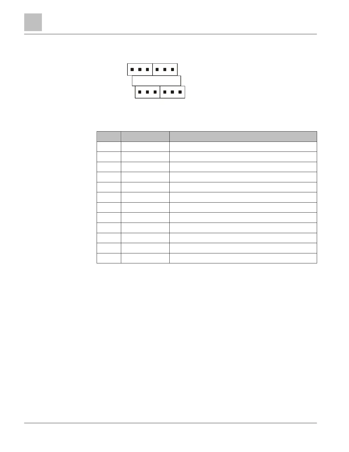
1.8.2 X1101 Relay terminal block
Pin Designation Description
1 C Common contact common alarm relay
2 NC Normally closed contact common alarm relay
3 NO Normally open contact common alarm relay
4 C Common contact common trouble relay
5 NC Normally closed contact common trouble relay
6 NO Normally open contact common trouble relay
7 C Common contact common supervisory relay
8 NC Normally closed contact common supervisory relay
9 NO Normally open contact common supervisory relay
10 C Common contact programmable relay
11 NC Normally closed contact programmable relay
12 NO Normally open contact programmable relay
Admissible cable cross-section: 1 x 12…18 AWG or 2 x 16…18 AWG
NO/NC (normally open / normally closed) relates to the fire detection system's normal
status.
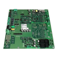
1.9 Detector circuits, circuit driver 1 (circuits 1 and 2)
The periphery board (250p) has one independent integrated circuit card. This
integrated card is a driver that has 2 circuits that can handle a maximum of 252
devices. Circuit driver 1 supports circuits 1 and 2 and can be configured for two circuits
(style 6) or four circuits (style 4).
The detector circuits are isolated from the periphery board's main circuit. The circuit
card has its own microprocessor for supervising ground fault, short-circuit, open circuit,
and line capacity.
1
6
7
12
C NCNO
TroubleAlarm
User
Supervisory
NCNO
C NC NO C NC NO