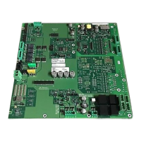
Periphery board (500p) FCI2017
2
33 |
Building Technologies
2.4.6 X303 Battery terminal
A cable harness is required to connect batteries to the periphery board. The battery
connector end that goes on the periphery board at X303 can only connect one way
because it is keyed.
The battery connection is only made once the whole system has been configured
through jumpers and modules, and after AC has been applied.
Pin Designation Description
1 BAT (+) DC 24 V feed for battery (RED WIRE)
2 BAT (-) Return (Ground) feed for battery (BLUE WIRE)
Admissible cable cross-section: 1 x 12…18 AWG or 2 x 16…18 AWG
The hardware required to connect the batteries to the periphery board is in the battery
kit.
2.5 NAC circuits
The periphery board has an NAC circuit that can be configured for 1 class A (style Z)
or 2 class B (style Y) circuits. Configuration is done via 3 jumpers (X604, X605 and
X606).
The NAC circuit can be configured such that, when
degraded mode is active, the
NAC circuit is activated by an alarm in the case of a CPU error on the periphery
board.
For the status of degraded mode during an active alarm, NAC activation is set by the
jumpers X602 and X603.
The outputs are power limited and are supervised for short-circuit and open circuit.
They are protected against direct short-circuit of the output terminals.
The synchronization protocol is built into the panel, so no module is needed.
The NAC is configured in the Engineering tool set. This includes the output pattern and
class A/B selection. Please note that the periphery board also has three jumpers (X604,
X605 and X606) that must match the settings in the Engineering tool set. If they do not
match, a trouble will post on the system.
The end-of-line resistor is 2.4 kΩ, 1/2 W.
These circuits are for NAC circuits NFPA 72 Local only. For NFPA 72 Municipal Tie or
NFPA 72 Leased Line, use the leased line/city tie module FCI2020. The module
connects to X902.
You will find information on the installation in the following documents:
● A6V10315015 for Desigo
● A6V10333409 for Cerberus PRO
You will find information on the configuration in the following documents:
● A6V10315023 for Desigo
● A6V10333423 for Cerberus PRO
 Loading...