4 | 46
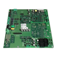
2 Periphery board (500p) FCI2017 ................................................................ 25
2.1 Description ......................................................................................................25
2.2 Installation .......................................................................................................27
2.3 Views ..............................................................................................................28
2.4 Configuration input power and battery ..............................................................30
2.4.1 Wiring power supply input and battery ...............................................30
2.4.2 X301 Power supply terminal block 1 ..................................................31
2.4.3 X302 Power supply 2 terminal block ..................................................32
2.4.4 X305 jumper – Power supply 2 on/off ................................................32
2.4.5 X304 Voice supply +24 V ..................................................................32
2.4.6 X303 Battery terminal .......................................................................33
2.5 NAC circuits.....................................................................................................33
2.5.1 Wiring the NAC circuits .....................................................................34
2.5.2 X601 terminal block – NAC 1 class A / NAC 1-1 class B /
NAC 1-2 class B ...............................................................................34
2.5.3 X602 jumper – ENABLE/DISABLE DEGRADED MODE for
NAC 1 class A or NAC 1-1 class B ....................................................35
2.5.4 X603 jumper – ENABLE/DISABLE DEGRADED MODE for
NAC 1-2 class B ...............................................................................35
2.5.5 X604, X605, X606 Jumper – NAC 1 class A/B ...................................35
2.5.6 X403 jumper – DEGRADE ALARM SILENCEABLE ...........................36
2.6 Bell follower input ............................................................................................36
2.6.1 Wiring ...............................................................................................36
2.6.2 X801 Bell follower terminal block .......................................................36
2.7 Auxiliary DC 24 V output ..................................................................................37
2.7.1 Wiring ...............................................................................................37
2.7.2 X1001 Auxiliary output terminal block ................................................37
2.8 Relays .............................................................................................................37
2.8.1 Wiring ...............................................................................................38
2.8.2 X1101 Relay terminal block ...............................................................38
2.9 Detector circuits, circuit driver 1 (circuits 1 and 2) and
circuit driver 2 (circuits 3 and 4) .......................................................................38
2.9.1 Wiring ...............................................................................................39
2.9.2 X1401 and X1801 terminal block – detector circuits 1 and 3 ..............40
2.9.3 X1402 and X1802 terminal block – detector circuits 2 and 4 ..............40
2.10 Indicators.........................................................................................................41
2.11 Reset Buttons ..................................................................................................41
2.11.1 S100 RESET periphery board ...........................................................41
2.12 Technical data .................................................................................................42
3 FCC Statement ........................................................................................ 45