DESCRIPTION 1-13
CHAPTER 1 | FIREFINDER-XLS INSTALLATION, OPERATION AND MAINTENANCE MANUAL
12345678
12345678
910111213141516
910111213141516
1
2
3
4
5
6
7
8
9
0
1
2
3
4
5
6
7
8
9
0
TB2
TB1
P2
S1 S2
P3
TB3
1
1
6
6
TB4
SIM-16
X
H
24 V
TB1
P1
P3
P4
TB2
RNI
TB3
TB4
TB5
TB6
JP1
P6
S1
P5
P7
OFF
ON
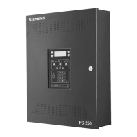
PSX-12 Power Supply The PSX-12 is a high current power supply extender.
Extender The power supply extender works in conjunction with the
PSC-12 power supply to provide an additional 12A of
regulated 24VDC for internal or external system use. Up to
three PSX-12 modules may be connected to one PSC-12
power supply and one set of batteries. The PSX-12 has a
microprocessor-controlled transfer circuit that allows it to
switch the system power to stand-by batteries during loss
or reduction of the AC power.
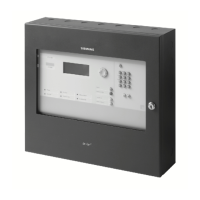
REMBOX 2/4 Remote The REMBOX2 and REMBOX4 Enclosures are used to
System Enclosure house a remote PMI/PMI-2/PMI-3 or CAN modules
(FCM/LCM/SCM/OCM/SIM). The REMBOX consists of
an outer door, an inner door, and a backbox.
The outer door and inner door are permanently hinged left.
The REMBOX has a
3
/4 inch flange on all four sides of the
enclosure which is used for flush mounting applications.
The backbox is mounted on a flat surface with four
user-supplied bolts that are a maximum of ¼ inch in
diameter.
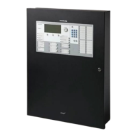
RNI Remote Network The RNI allows for the remote installation of the PMI/PMI-2/PMI-3 (on
Interface HNET) and the LCM-8/SCM-8/FCM-6/SIM-16/OCM-16 (on CAN)
modules. The HNET can be wired either Style 4 or Style 7. The RNI may
be placed in the middle or at the end of either the HNET or CAN
networks.
In Canada, ULC S524 requires that all interconnecting data communi-
cations links for networks be wired DCLC (style 7) except for dedi-
cated network communication to annunciators.
The RNI mounts in the rear of either the REMBOX2 or REMBOX4
enclosures. The RNI provides terminal blocks for all field wiring connec-
tions. Internal connections are made to plug in connectors
specifically provided for each of the installed modules.
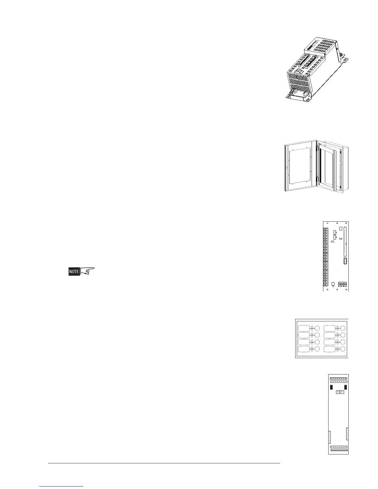
SCM-8 Switch Control The SCM-8 contains eight switches and eight pairs of LEDs.
Each pair contains one bi-color (red/green) and one yellow
LED. The functions of the switches and LEDs are pro-
grammed using the Zeus Tool (Refer to the Zeus Quick Start
Guide, P/N 315-033875). All LEDs can be programmed ON, OFF, or
FLASHING. The SCM is used for manual control of the systems.
SIM-16 Supervised Input The SIM-16 is a remotely located, general purpose input module. It
provides sixteen input circuits for remote system monitoring. Each
input can be individually programmed as supervised (dry contacts only)
or unsupervised (general-purpose input). The SIM-16 has two Form C
relays. The relays and the inputs are programmable using the Zeus
programming tool.
 Loading...