Siemens Industry, Inc.
Building Technologies Division
P/N 315-034860-136
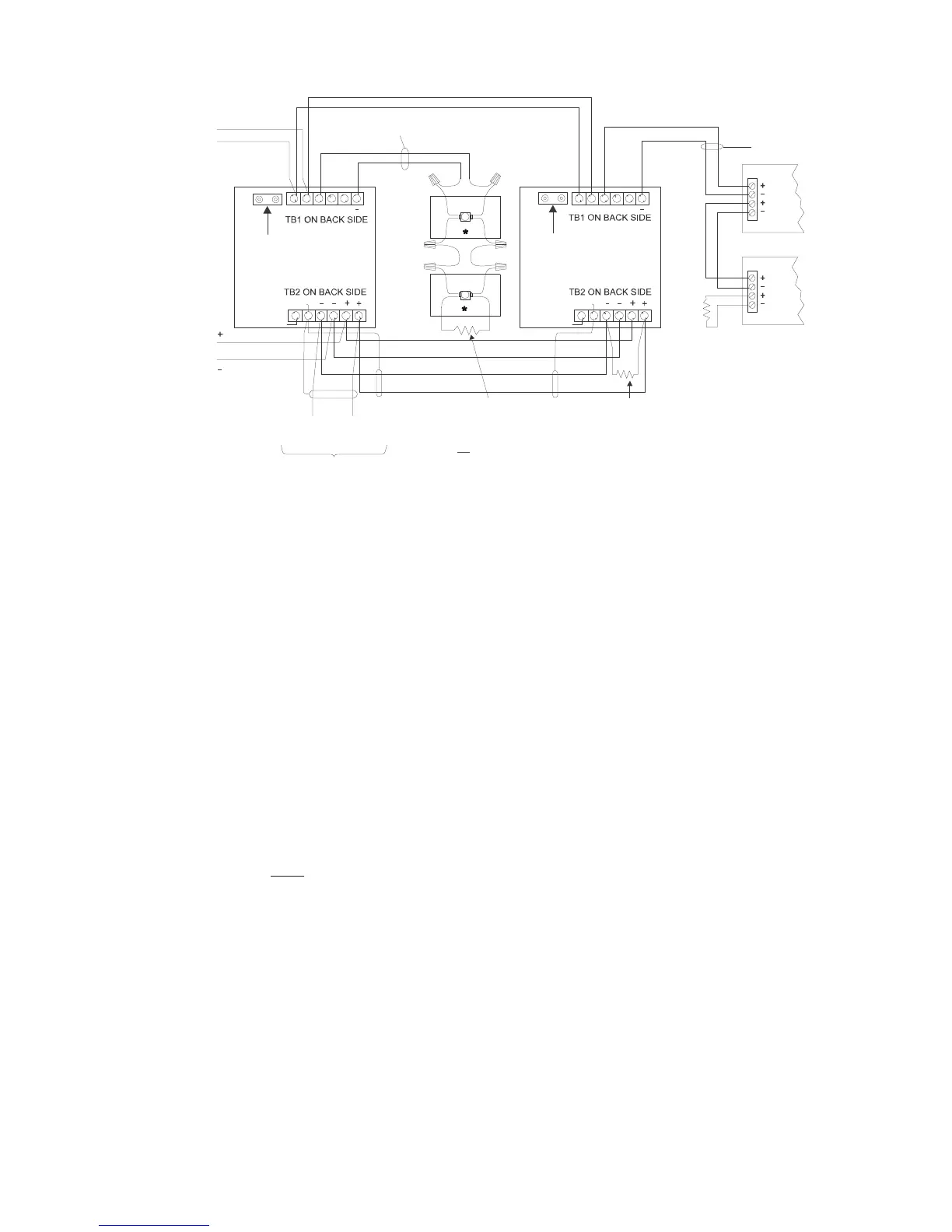
POSITIVE AND NEGATIVE GROUND FAULT
DETECTED AT <500 OHMS FOR
TERMINALS 3-6 ON TB1.
75K, ¼W, +/-5%
EOL RESISTOR
P/N 140-050797
AT LAST FJ-303
FROM PREVIOUS HCP OR TZC-8B
(100 OHMS MAXIMUM
LINE RESISTANCE)
COMMON TALK RISER
(POWER LIMITED)
SEE TZC-8B INSTALLATION
INSTRUCTIONS, P/N 315-034110,
FOR RISER RATINGS
ELECTRICAL:
INPUT DC SUPPLY: 18.8 - 28.2VDC,
30mA MAX
FILTERED FULL WAVE
NOTES:
1. THE SHIELD ON THE COMMON TALK
LINE MUST BE CONTINUOUS AND
CONNECTED ONLY TO EARTH
GROUND AT CONTROL PANEL.
2. ALL WIRING MUST COMPLY WITH
NATIONAL AND LOCAL CODES.
3. 12-18 AWG OR AS REQUIRED
BY THE LOCAL AUTHORITY
HAVING JURISDICTION.
HCP DC SUPPLY
FROM PSC-12 (TB-3),
PSX-12 (TB-3),
OR PAD-4* (TB16)
75K, ¼W, +/-5%
EOL RESISTOR
P/N 140-050797
AT LAST STATION
10K, 1/2W, +/-5%
EOL RESISTOR
WARDEN’S STATIONS
(FTS SERIES)
SUPERVISED, 24 OHMS MAX
UNSHIELDED, USE TWISTED PAIR
SUPERVISED
24 OHMS MAX
UNSHIELDED
USE TWISTED PAIR
FROM DLC DEVICE
LOOP IN CC-5 / CC-2
POWER LIMITED
SHIELD
*
REMOVE 10K TERMINATING RESISTORS FROM THE FJ-303sALL
SHIELD
WHITE
BLACK
WHITE
SHIELD
SHIELD
TO
EARTH
SHIELD
BLACK
WHITE
BLACK
WHITE
BLACK
HCP HCP
TO
EARTH
FJ-303
1 2 3 4 5 6
6 5 4 3 2 1
6 5 4 3 2 1
1 2 3 4 5 6
FJ-303
LINE 1
LINE 2
PROGRAMMING
POINTS
PROGRAMMING
POINTS
+
+
*REFER TO PAD-4 INSTALLATION INSTRUCTIONS, P/N 315-050217, FOR PROPER SETTING OF SWITCH 4. THE AUXILIARY POWER OUTPUT MUST BE CONFIGURED TO “ALWAYS ON”.
Figure 6
HCP Used As A Telephone Zone
HCP As (70.7V/25V) Speaker Zone in an XLSV System
When the HCP is used as a speaker zone (FireFinder-XLS System only), the 24 VDC
provides power to the supervision circuitry. If the 24 volts is lost or there is an open
or shorted speaker output line, a trouble condition displays on the PMI/PMI-2 of the
FireFinder-XLS.
The 70.7V/25V RMS audio input to the HCP must be power limited, such as from the
ZAC-40. The ZAC-40 supervises the audio connection path to the HCP and provides
up to 40 watts of power. The ZAC-40 can be wired Style Y (Class B) only. Refer to the
ZAC-40 Installation Instructions, P/N 315-035400 for further information. In order to
function properly during degrade mode, the DLC to which the HCP is connected
must be located in the same enclosure as the DAC-NET and ZAC-40 that supply
audio to the HCP.
When the HCP is used as a speaker zone, the output speaker lines are only super-
vised when the zone is not active. The audio output must not be allowed to exceed
25 watts. The approximate decibel loss for the total speaker zone wire length for
various wire gauge sizes is shown in Figure 7 for the 70.7V option and in Figure 8 for
the 25V option. Connect the speaker output as Style Y (Class B) as shown in Figure 9.
 Loading...


