Do you have a question about the Siemens LMV50 series and is the answer not in the manual?
Key functions include burner control, fuel-air ratio, and boiler load control.
Crucial warnings to prevent injury, damage, or environmental harm.
Guidelines for proper installation and mounting.
Important considerations for electrical wiring and compliance.
Characteristics of the burner control's inputs and outputs.
Details on flame signal inputs and detector types.
Description of various digital input functionalities.
Input for the safety loop, directly switching off fuel valves and ignition.
Functionality for manual system lockout and reset.
Input for gas pressure monitoring and valve status.
Description of various digital output functionalities.
Description of the burner control sequence.
Important time parameters for sequence control.
Parameters defining reaction time to flame loss and safety time.
Function to ensure gas valves are not opened when a leak is detected.
Mapping of actuators to addresses for FARC system.
Procedure for activating or deactivating actuators for FARC.
Step-by-step operation of the fuel-air ratio control system.
Configuration and operation of multistage burners.
Ensuring actuators reach positions within safety time limits.
Setting minimum and maximum burner output limits.
Defining actuator positions upon lockout or shutdown.
Protection against actuator damage due to overload.
Configuration options for load controller operation.
Procedure for manually configuring PID parameters.
Automatic adjustment of PID parameters.
Safety function to limit temperature and prevent overheating.
Protection against thermal shock during cold starts.
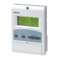
Navigating and adjusting settings via the AZL5 display.
Hierarchical organization of the AZL5 menu system.
Information on displaying lockout and error messages.
Procedure for setting standard parameters with password.
Steps for addressing actuators and assigning functions.
Detailed guide for setting FARC curves.
Automatic adjustment of PID parameters for load control.
Steps for configuring the VSD based on motor type.
Setting up the speed sensor for acquisition.
Procedure for standardizing the VSD speed.
Explanation of how the O2 trim control system operates.
Function of precontrol in reducing air rate changes.
Different operating modes for O2 trim control.
Description of various modes for O2 trim control and alarm.
Specific burner start modes for O2 trim control.
Steps for initializing and releasing the O2 trim controller.
Setting safety limits for the manipulated variable.
Using a contact input to deactivate O2 trim control.
Configuration and operation of the O2 alarm system.
Conditions that trigger the O2 alarm to switch off.
Configuration and behavior of the O2 minimum value alarm.
Configuration and behavior of the O2 maximum value alarm.
Methods for inactivating or deactivating the O2 alarm.
Steps for performing the O2 sensor test.
Initial configuration steps for the LMV5 system.
Setting the unique burner identification code.
Configuring the gas valve proving safety function.
Steps for addressing actuators and assigning functions.
Specific settings required for gas-fired operation.
Checking and setting actuator positions for gas ignition.
Specific settings for multistage oil-fired operation.
Procedure for testing valve integrity and detecting leaks.
Detailed steps for configuring the load controller.
Defining and adjusting control parameters for the load controller.
Manually setting PID parameters for the load controller.
Using the adaption function for automatic PID tuning.
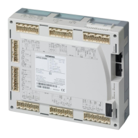
Information on physical terminal connections and coding.
Detailed description of AC 120V terminal connections.
Detailed description of AC 230V terminal connections.
Essential guide for installation, wiring, and servicing.
Information on powering the LMV5 unit via transformer.
How the flue gas recirculation function works to reduce NOx.
Parameters controlling the flue gas recirculation function.
Integrating FGR with electronic fuel-air ratio control.
| Brand | Siemens |
|---|---|
| Model | LMV50 series |
| Category | Laser Level |
| Language | English |