32/327
Building Technologies Basic Documentation LMV5... CC1P7550en
4 Burner control 22.05.2018
4 Burner control
4.1 Description of inputs and outputs
This chapter describes the basic characteristics of the burner control’s inputs and
outputs. For the valuation of inputs and the activation of outputs, refer to Sequence
diagrams.
4.1.1 Flame signal input and flame detector
The following connection facilities are provided:
∂ QRI (infrared flame detector) for continuous or intermittent operation
∂ Ionization probe for continuous or intermittent operation
∂ QRB flame detector for intermittent operation only
∂ QRA2 / QRA4 / QRA10 flame detector with AGQ1 for intermittent operation at AC
120 V / AC 230 V
∂ QRA7 for continuous or intermittent operation
Caution!
Continuous operation with the QRA2/QRA4/QRA10 with AGQ1 and QRB is not
possible!
Caution!
Do not use terminal X10-02 pin 1. This also applies to the connection of idle lines if
the LMV5 is used for continuous operation!
Caution!
The response time of flame detector leads to a prolongation of the second
safety time!
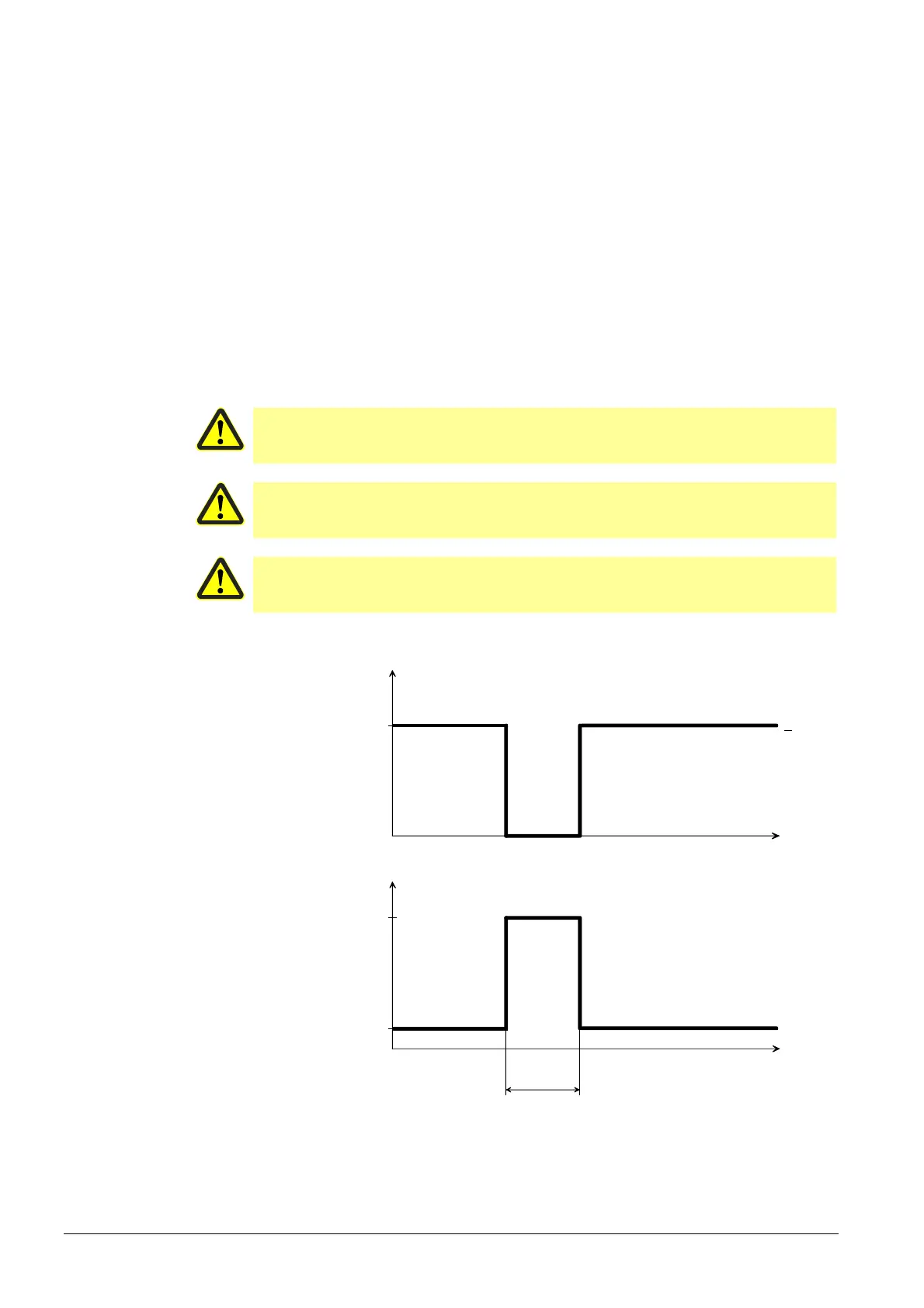
4.1.1.1 Self-test function LMV5 / QRI / QRA7
t
<DC 5,5 V
21 V
Test time
Signal
voltage
Self-test
voltage
QRA7... / QRI...
Supply voltage
(operation)
QRI...
14 V
Figure 24: Self-test function LMV5 / QRI / QRA7
Flame signal input
and flame detector
X10–01 and X10–03
 Loading...