37/327
Building Technologies Basic Documentation LMV5... CC1P7550en
4 Burner control 22.05.2018
4.1.1.6 QRA7 (suited for continuous operation)
Supply voltage
- QRA73A17 / QRA75A17
- QRA73A27 / QRA75A27
AC 120 V
AC 230 V
Power supply for test via increasing the
power supply for QRA7
(X10-02 pin 2)
From DC 14 V up to DC 21 V
Required signal voltage
(X10-02 pin 6)
Min. DC 3,5 V
Display flame approx. 50%
(with factory setting of the parameter
StandardFactor)
Possible signal voltage (X10-02 pin 6) Max. DC 5,5 V
Display flame approx. 100%
(with factory setting of the parameter
StandardFactor)
Permissible signal voltage during
extraneous light test (X10-02 pin 6)
Max. DC 0,3 V
Perm. length of detector cable
- 6 wire cable
- Signal cable no. 3, 4 and 5
Max. 10
Max. 100 m (laid separately from L, N and
PE as shielded cable)
Cable AGM23...
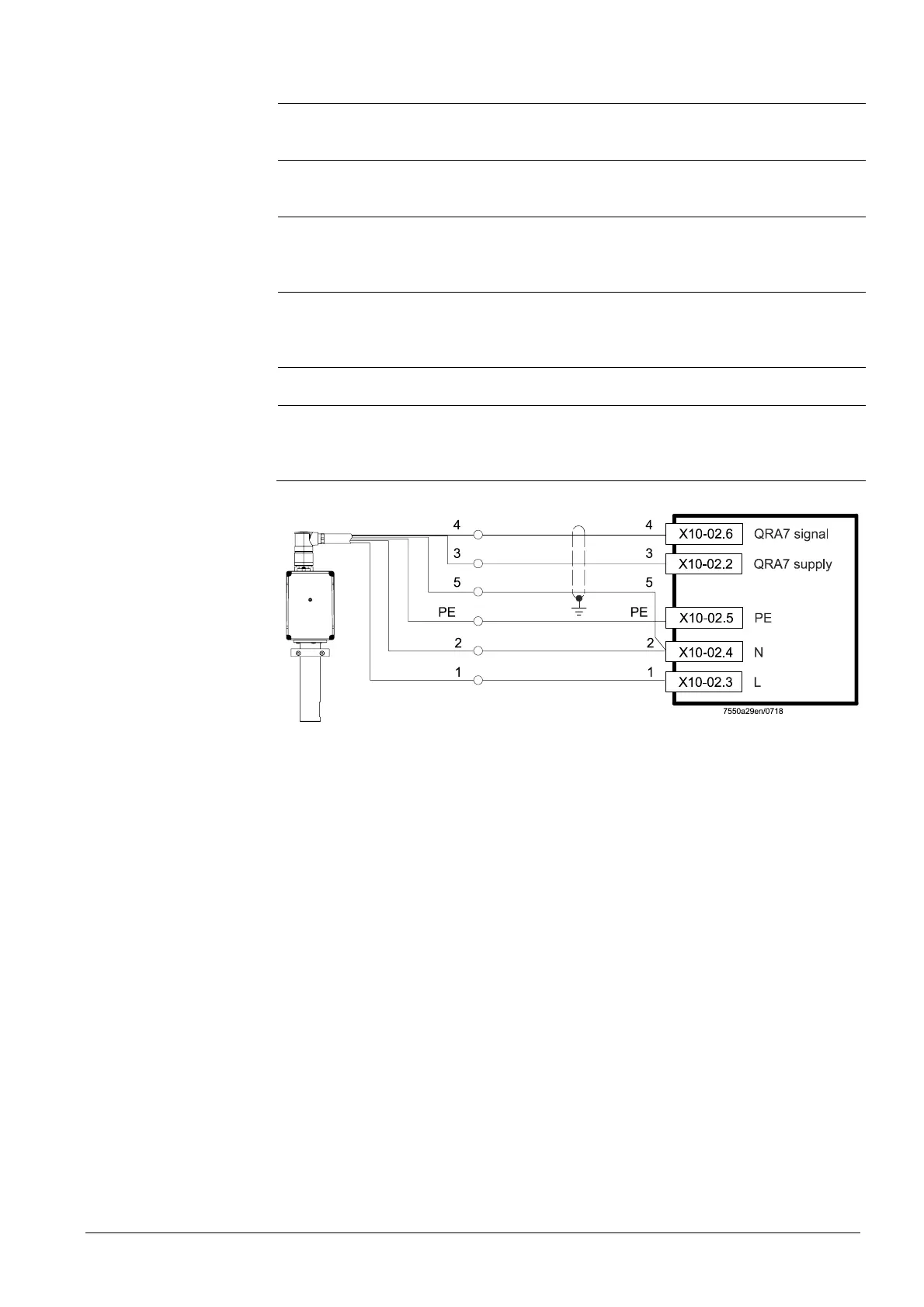
Figure 27: Connection diagram QRA7 with cable AGM23
For more detailed information about QRA7, refer to Data Sheet N7712.
Connection diagram
 Loading...