294/327
Building Technologies Basic Documentation LMV5... CC1P7550en
20 Flue gas recirculation (FGR) function (LMV50/LMV51.3/LMV52) 22.05.2018
Only LMV52.4:
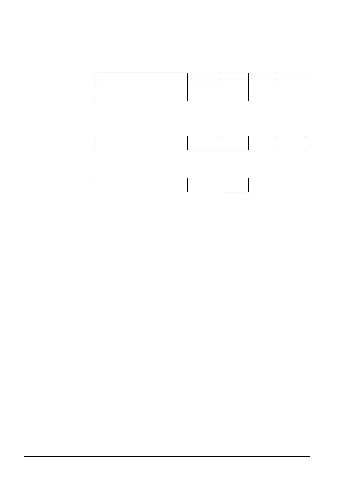
Examples of tables showing the damper positions with flue gas recirculation
(FGR)
Table with setting values:
Output 37.5% 62.5% 75% 100%
Flue gas recirculation (FGR) curve 19.3° 25.0° 28.5° 37.0°
Flue gas recirculation (FGR)
temperature
72 °C 105 °C 121 °C 150 °C
The LMV52.4 uses these setting values to calculate a zero curve:
Example of flue gas recirculation (FGR) positions calculated by the LMV52.4 for a flue
gas recirculation (FGR) factor of 100%:
Position flue gas recirculation with
T = 0 °C zero curve
15.2° 18.0° 19.7° 23.8°
Example of flue gas recirculation (FGR) positions calculated from the identical setting
values for a flue gas recirculation (FGR) factor of 50%:
Position flue gas recirculation with
T = 0 °C zero curve
7.6° 9.0° 9.8° 11.9°
The above example shows that – with the zero curve – a flue gas recirculation (FGR)
factor of 50% leads to a 50% reduction of the damper positions.
The LMV52.4 performs a linear interpolation of the damper positions between the
setting values and the zero curve, depending on the current flue gas temperature.
When the flue gas temperatures lie above the setting values, the calculated damper
positions are higher than the setting values.
 Loading...