326/327
Building Technologies Basic Documentation LMV5... CC1P7550en
24 List of figures 22.05.2018
Figure 70: Connection for several LMV5s to SIMATIC S7-1200 via separate Modbus
connections .......................................................................................................... 136
Figure 71: Connection for LMV5 to ET 200S via Modbus ........................................... 137
Figure 72: Connection for several LMV5s to ET 200S via common Modbus ............. 137
Figure 73: Connection for several LMV5s to ET 200S via separate Modbus connections
............................................................................................................................. 137
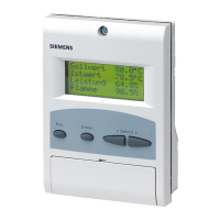
Figure 74: Display and settings ................................................................................... 139
Figure 75: Addressing the actuators ........................................................................... 149
Figure 76: LED function code ..................................................................................... 150
Figure 77: Addressing completed ............................................................................... 150
Figure 78: Adjustment of the actuator positions via the load with automatically entered
point ..................................................................................................................... 157
Figure 79: Adjustment of the actuator positions via the load with 2 points ................. 157
Figure 80: Adjustment of the actuator positions via the load with multiple points ....... 158
Figure 81: Fuel-air ratio control ................................................................................... 174
Figure 82: Fuel-air ratio control – multistage operation .............................................. 180
Figure 83: Extra functions of the LMV5 ....................................................................... 181
Figure 84: 2-position controller ................................................................................... 187
Figure 85: Cold start thermal shock protection ........................................................... 188
Figure 86: Connection terminals LMV51.040x1 .......................................................... 190
Figure 87: Connection terminals LMV51.000x1 / LMV51.000x2 / LMV51.040x2 ....... 191
Figure 88: Connection terminals LMV51.140x1 .......................................................... 192
Figure 89: Connection terminals LMV51.100x1 / LMV51.100x2 / LMV51.140x2 ....... 193
Figure 90: Connection terminals LMV51.300x1 / LMV51.300x2 / LMV52.200x1 /
LMV52.200x2 / LMV52.240x2 / LMV52.400x1 / LMV52.400X2........................... 194
Figure 91: Connection terminals LMV51.340x1 / LMV52.240x1 / LMV52.440x1 /
LMV52.440X2 ...................................................................................................... 195
Figure 92: Coding of connectors ................................................................................. 196
Figure 93: Connection of LMV5 CAN bus ................................................................... 213
Figure 94: Installation of all components in the burner; CAN bus cable LMV5
♠
last
actuator <20 m ................................................................................................. 215
Figure 95: LMV5 in the control panels, actuator on the burner; CAN bus cable LMV5
↑
last actuator >20 m ........................................................................................... 216
Figure 96: Installation of all components in the burner; CAN bus cable LMV52
♠
last
actuator >20 m with 6 actuators and PLL52 ........................................................ 217
Figure 97: Installation in the control panel, actuator on the burner and the boiler; CAN
bus cable LMV52
♠
last actuator >25 m with 4 actuators and PLL52 ................ 217
Figure 98: Installation in the control panel, the burner and on the boiler; CAN bus cable
LMV52
♠
last actuator >25 m with 4 actuators and PLL52 ................................ 218
Figure 99: Installation of all components in the burner; CAN bus cable LMV52
♠
last
actuator <20 m with 4 actuators and PLL52 ........................................................ 219
 Loading...