74/327
Building Technologies Basic Documentation LMV5... CC1P7550en
5 Sequence diagrams 22.05.2018
0° / 0%
TSA1
TSA2
X4-01 Pin 1
X3-04 Pin 1
X60 Pin 1 / 3
X5-03 Pin 1
X3-02 Pin 1
X4-01 Pin 3
X4-01 Pin 3
X7-03 Pin 2
X9-03 Pin 2
X7-03 Pin 2
X9-03 Pin 2
X9-03 Pin 4
X9-03 Pin 3
X3-01 Pin 1
X4-02 Pin 3
X4-03 Pin 3
X4-03 Pin 3
X4-03 Pin 3
X3-01 Pin 2
X9-01 Pin 1
X9-01 Pin 2
X7-03 Pin 2
X9-03 Pin 2
X9-01 Pin 3
X9-01 Pin 4
P
P
P
P
P
1) 1)
X6-01 Pin 1
X6-01 Pin 3
X6-01 Pin 1
X6-01 Pin 3
Redundancy contact
External flame safeguard
External flame safeguard
Shutdown
Timer - Result - Relationship
Timer 1
Timer 2
Timer 3 = Phase max. time
Operating mode gas
Controller ON / OFF
Flame signal 20)
Air pressure switch
Fan contactor contact
Flue gas recirculation
pressure switch
Gas + oil
Fan motor
Ignition
Shutoff valve
ACTUATORS
CPI gas
CPI oil
Pressure switch release
Pressure switch release
inverse
Fuel
Actuators
Gas (address 2)
Oil (address 3)
Air, AUX,
VSD
Actuators
Air (address 1)
AUX1 (address 4)
AUX2 (address 5)
VSD
NOx-red.
Actuator
AUX3 for FGR
(address 6)
Function inputs
RAST plug
pin number
RAST plug
pin number
Fuel valve 2
Fuel valve 1
Cooling function 27)
CPI gas + oil
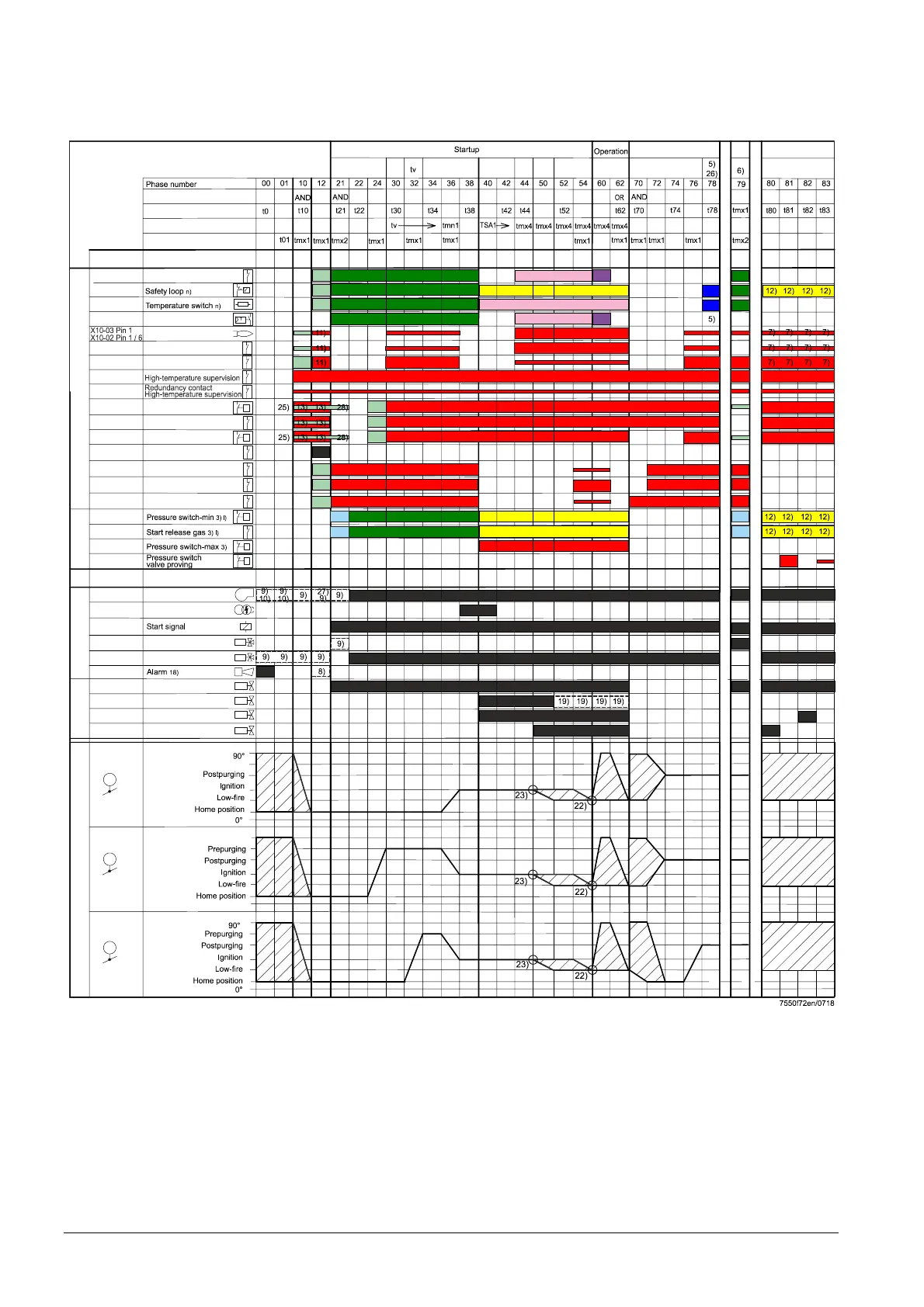
Figure 32: Fuel train application – program gas direct ignition (Gp1)
Gas pilot ignition 1 (Gp1)
 Loading...