Siemens Elema AB Register 6 SPB7-230.051.07 Page 6 of 14 M1000/3000 Nova
Solna, Sweden Rev. 02 03.00 SPS-UD Wiring Diagrams
4-6 X041E
Switches 0
Potentiometers 0
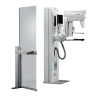
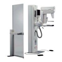
Fig. 12 Separate Control Console
Switch Page Origin Description
S1 5-11/3D D701 Test switch for factory use
Reset 5-11/2D D701 Reset of D701
S1 5-5/2D D702 UZW OFF/ON ON=Upper position
S2 5-5//2D D702 SS OFF/ON ON=Upper position
S3 5-5/3D D702 For service PC connection:
ON= Upper position
For serial printer connection:
OFF=Lower position
S1 5-7/1E D706 Manual activation of Power aid unit
S1 5-3/2F D711 System ON (Parallell with D741/S2)
S2 5-3/2F D711 System OFF (Parallell with D741/S1)
S27A, S27B 5-10/3A D740 Preparation and exposure release buttons
S1 5-3/2G
5-10/1B
D741 System OFF
S2 5-3/2G
5-10/1B
D741 System ON
S3 3-12/5F Separate control
console
Decompression button
Potentiometers Page Origin Description
R5 5-7/3D D706 Adjustment of bias voltage for Molybden (Mo)
R4 5-7/3D D706 Adjustment of bias voltage for Tungsten (W)
R43 5-5/4D D702 Adjustment of kV
Decompression button
LIST OF SWITCHES AND COMPONENTS, GENERATOR

 Loading...


