EasyManuals Logo

Siemens Maxum II Service Manual

Siemens Maxum II
58 pages
To Next Page IconTo Next Page
To Previous Page IconTo Previous Page
Page #24 background imageLoading...
Page #24 background image
The method is the part of the application that contains the parameters for controlling the
hardware used by one cycle clock. It provides peak areas and component concentrations and
includes all cycle clock timed events. There is one cycle clock per method.
Status
LEDs
Access hole for mounting
screw for Temp Setpoint modules
Ignite Signal/
Igniter Power
Location
ID Switch
RTD Temp Control Input
Flame Sense and
Filament Detector Input
Signal Cable
from Detector
Mezzanine
Module
Mounting
Location
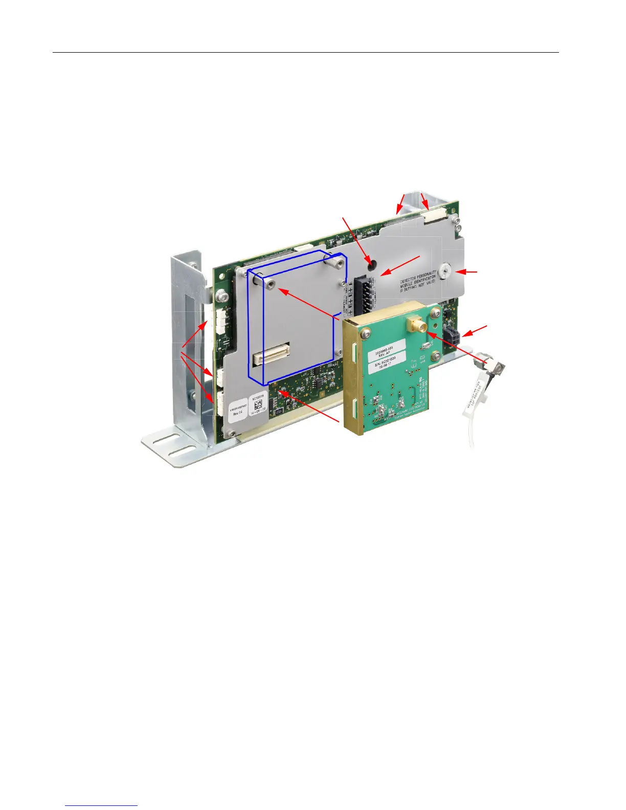
Figure 3-5 Base3DPM With Mezzanine Module
Part Number
The Base3 DPM (Part Number A5E02645925001) is shipped with current analyzers. It can
be used as a replacement part for earlier DPMs in Maxum I analyzers using an adapter, part
number A5E34938458001.
Flame Photometric Detector
3.5 Base3 Detector Personality Module (DPM)
Maxum Edition II Detectors
24 Service Manual, May 2018, A5E42019847001

Other manuals for Siemens Maxum II

Questions and Answers:

Question and Answer IconNeed help?

Do you have a question about the Siemens Maxum II and is the answer not in the manual?

Siemens Maxum II Specifications

General IconGeneral
CategoryGas Chromatograph
Measurement PrincipleGas Chromatography
Communication ProtocolsModbus, Ethernet, Profibus
Operating Temperature-20°C to 55°C
Power Supply24 VDC or 100-240 VAC
Mountingrack mount
ApplicationsRefinery, chemical, petrochemical, natural gas
DetectorsThermal Conductivity Detector (TCD), Flame Ionization Detector (FID)
Sample InletsMultiple
DimensionsVaries by configuration (e.g., 19" rack mount)

Related product manuals