EasyManuals Logo

Siemens Maxum II Service Manual

Siemens Maxum II
58 pages
To Next Page IconTo Next Page
To Previous Page IconTo Previous Page
Page #26 background imageLoading...
Page #26 background image
Detector Control Paths
Several control signals are available to control various detector functions as shown below.
5 V Power (FPD)
Enable (FPD)
300 V Bias (FID)
Digital (Ignite) / Power (Glow Plug)
Network
I
2
C
I
2
C
Digital
(Range
Select)
GCP
Color
Touch
Display
SYSCON
PECM
BaseDPM
A/D
Mezzanine
Module
(signal conditioning)
FID
FPD
Analog
Output
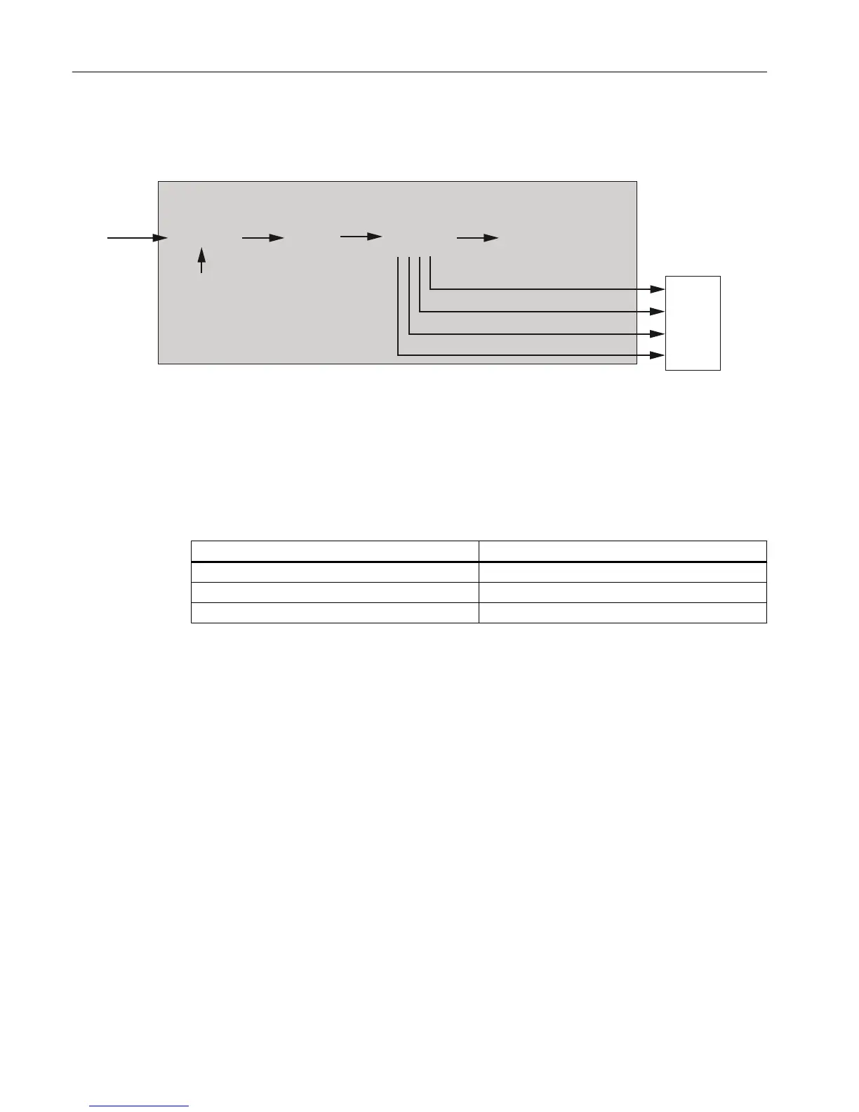
Figure 3-8 Maxum II Detector Control Functions
Location ID Switch
The Location ID Switch, shown previously in the photograph, selects the DPM location that is
incorporated in the address, to be reported in the results.
The DPM I
2
C port is connected directly to the system controller via the PECM or a wiring
distribution board. In this scenario, the following values are applied:
Switch Value Location
1 Left
2 Center
3 Right
NOTE:
If the DPM I
2
C port is connected to an SNE, the value is always set to “1”. The actual location
value is determined by the SNE.
Flame Photometric Detector
3.5 Base3 Detector Personality Module (DPM)
Maxum Edition II Detectors
26 Service Manual, May 2018, A5E42019847001

Other manuals for Siemens Maxum II

Questions and Answers:

Question and Answer IconNeed help?

Do you have a question about the Siemens Maxum II and is the answer not in the manual?

Siemens Maxum II Specifications

General IconGeneral
CategoryGas Chromatograph
Measurement PrincipleGas Chromatography
Communication ProtocolsModbus, Ethernet, Profibus
Operating Temperature-20°C to 55°C
Power Supply24 VDC or 100-240 VAC
Mountingrack mount
ApplicationsRefinery, chemical, petrochemical, natural gas
DetectorsThermal Conductivity Detector (TCD), Flame Ionization Detector (FID)
Sample InletsMultiple
DimensionsVaries by configuration (e.g., 19" rack mount)

Related product manuals