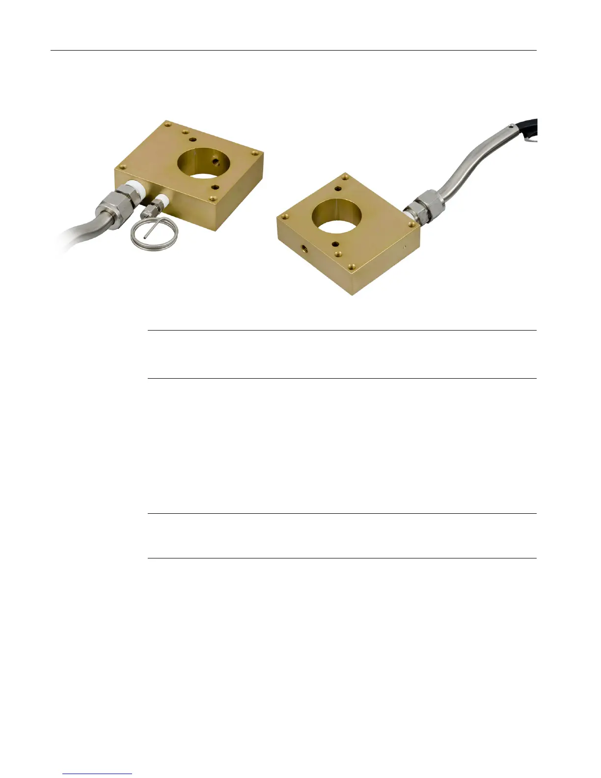
Figure 4-11 Heater Assembly
Note
Do not disassemble the heater block assembly.
Disassembling the heater block voids the ‘hi-pot’ testing.
7. Install the Kalrez high-temperature O-ring (A6X19905099) into the groove on the new purge
tube bushing. See New Bushing (with Tab for Connecting Strap).
8. Install the new purge tube bushing (A5E41666802001) onto the FID using the 4 screws
removed from the purge tube earlier in this procedure. The new pipe gasket
(A5E41666941001) should be positioned between the bushing and the FID body. Install
the bushing such that the tab (used to attach the igniter fastening strap) is on the bottom.
9. Using a 2.5mm hex wrench, attach the mounting strap to the new igniter board. Use an M3
x 4 socket head cap screw (1312420-331) from the kit for this connection. See New Igniter
Attachment to Detector.
Note
Because the wires from the igniter to the electrodes are stiff, it is best to plug the wires in
before attaching the strap to the bushing.
10.Plug both igniter wires into the appropriate detector electrode positions. The wires from the
igniter board to the DPM should not be connected yet.
11.Using a 2.5mm Allen wrench, attach the new igniter board to the bushing on the detector
assembly using the fastening strap. Use a socket head cap screw (item 6) and lock washer
(item 7) from the kit for this connection. Note that the igniter board is installed with the flat
side up and the round transformer down. See New Igniter Attachmnment to Detector.
Flame Ionization Detector
4.4 Replacing the FID Igniter
Maxum Edition II Detectors
44 Service Manual, May 2018, A5E42019847001

 Loading...


