2 Using the MJ-XL Operator Panel and Controls
8 Siemens Power Transmission & Distribution, Inc.
the control program is returning the tap position to Neu-
tral.
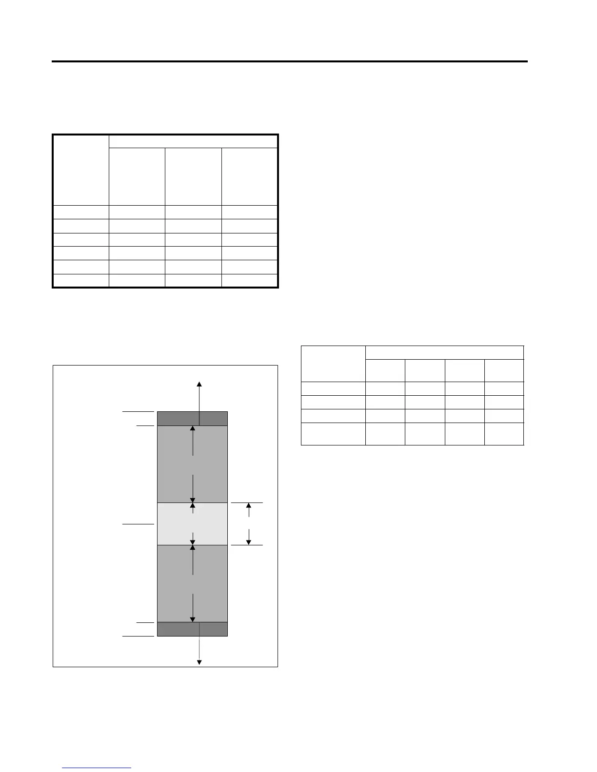
In the above table, the indicator that is flashing or is on
solid is the respective Band Indicator (High, Low, or In
Band). If all band indicators are off, it is an indication that
Voltage Limit Control (VLC) is active, and compensated
regulator output voltage is higher than the VLC upper
limit, or lower than the VLC Lower limit.
Figure 2.2 Band Indicators and VLC Indicators
Raise and Lower LED Indicators
The Raise indicator is on whenever the tap changer motor
is raising the tap position. The Lower indicator is on when-
ever the tap changer motor is lowering the tap position.
Voltage Limit Control LED Indicators
The Voltage Limit Control (VLC) indicators illuminate to
indicate that VLC is active. With the VLC upper limit acti-
vated, the VLC Upper indicator is illuminated. If the VLC
lower limit is activated, the VLC Lower indicator is illumi-
nated.
If VLC is active, and Vld is within 1 volt of the VLC limit,
the appropriate VLC and Band Indicator will both be illumi-
nated.
Voltage Reduction Control Active Indicator LED
This indicator is illuminated whenever Voltage Reduction
Control is in effect. The VRC LED indicator flashes a
unique pattern to indicate which stage, step, or set is
active, depending upon the VRC Mode as described in
Table 2.3. (See Section 4.4.3 for more information.)
Neutralite Indicator
The Neutralite indicator illuminates when the tap changer
is in the Neutral position. The Neutralite indicator also illu-
minates when the Neutralite Test key is pressed and held.
2.5 Switches
Power Switch
This three-position switch selects the power source for
the MJ-X
L
Control Panel.
• In the upper (Normal) position, the regulator Utility
(tertiary) winding provides power through the polar-
ized disconnect switch (PDS).
• In the lower (External Source) position, the External
Source terminals (described below) provide power.
• In the middle (Off) position, the MJ-X
L
Control Panel
is turned off. This is also called the By-Pass Position.
Table 2.2 Band Indicator Status
Power Flow
Mode
Band Indicator Status
RPF active
and current
magnitude
exceeds I
Threshold %
RPF or FPF
with current
magnitude
below I
Threshold %,
but not = 0
FPF active
and current
magnitude
exceeds I
Threshold %
Neutral R Flash Flash On solid
Idle R Flash Flash On solid
Co-Gen On solid Flash On solid
Bi-Dir On solid Flash On solid
F Lock Flash On solid On solid
R Lock On solid On solid Flash
VLC Upper
VLC Lower
Bandwidt
"In-Band"
Indicator
"High" Band
Indicator
VLC Upper
Indicator
"Low" Band
Indicator
VLC Lower
Indicator
Voltage Level
Setpoint
1 v
1 v
Table 2.3 VRC Indicator Flash Patterns
Flashing
Pattern
VRC Modes
Local Remote
(MJ-XL)
Remote
(MJ-3A)
Auto
On Active
long-short Stage-1 Step 1 Set 1
long-short-short Stage-2 Step 2 Set 2
long-short-
short-short
Stage-3 Step 3

 Loading...


